Vehicle Telematics VT310/320 User Manual (Standard Edition)
Front Matter
Copyright and Conventions
This user manual contains copyrighted content, and the copyright belongs to InHand Networks and its licensors. Without written permission, no organization or individual may excerpt, copy any part of the content of this manual, or distribute it in any form.
Due to ongoing updates in product technology and specifications, the company cannot guarantee that the information in the user manual is entirely consistent with the actual product. Therefore, no disputes arising from any discrepancies between the actual technical parameters and the user manual are accepted. Any changes to the product will not be notified in advance, and the company reserves the right to make the final changes and interpretations.
Conventions
| Symbol | Indication |
|---|---|
| > | Indicates a button name |
| "" | Indicates a window name or menu name |
| >> | Separates a multi-level menu |
| Cautions | Points to note during operation; improper actions may result in data loss or device damage |
| Note | Supplement and provide necessary explanations for the description of the operation |
Technical Support
Email: [email protected]
URL: www.inhand.com
How to Use This Manual
Find Your Path
- First-time users: Read in order: "Know the Device" → "Installation and First Use" → "Common Scenarios" → "Function Reference"
- Existing users: Go directly to "Function Reference" or "Appendix A Troubleshooting"
Quick Jump by Task
| Task | Section | Est. Time |
|---|---|---|
| Know the device and interfaces | 1. Know the Device | ~3 min |
| Power on and connect config tool | 2. Installation and First Use | ~10 min |
| Configure cellular network | 3.1 Cellular Configuration | ~5 min |
| Connect to cloud platform | 3.2 Cloud Platform Connection | ~10 min |
| Configure CAN, OBD, I/O, etc. | 4. Function Reference | As needed |
| Troubleshooting | Appendix A Troubleshooting | As needed |
1. Know the Device
1.1 Overview
The VT310/320 series vehicle tracking gateway is an asset tracking product that features cost-effectiveness, rich interfaces and strong performance. It is suitable for industries such as logistics and transportation, engineering vehicle monitoring and so on. It offers precise positioning with GNSS (Global Navigation Satellite System, can be understood as: satellite-based positioning system for location and time), tracking and monitoring the status, history track, geofencing, abnormity alarm and other functions of vehicles and drivers. Combined with the vehicle network cloud platform, it can realize remote vehicle management, asset tracking, preventive maintenance, helping fleet operators save costs and improve efficiency. The device provides sub-models that support wireless network access of various speeds such as LTE CatM1, Cat1, Cat4, etc.
1.2 Packing List
VT310 Standard: 1 device and 4 screws. Accessories need to be purchased separately.
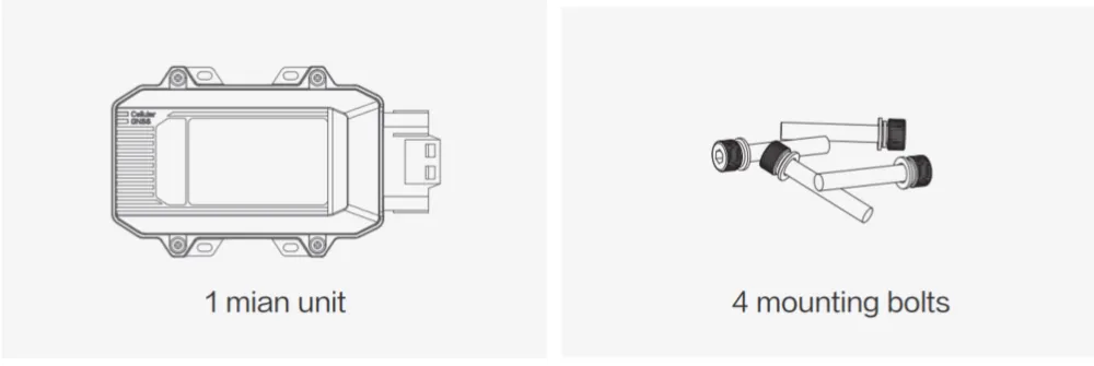
Fig. 1-1 VT310 Standard Packing
VT310 Optional Accessories
| Product Name | MLFB | Specifications |
|---|---|---|
| 26PIN all-in-one test cable | SCAB000229 | P1: 26PIN female to VT; P2: open end for 9–48 V adapter. For office testing. |
| OBD-II 7PIN all-in-one cable | SCAB000231 | P1: 26PIN to VT; P2: OBD-II male to vehicle; P3: ignition terminal. For heavy trucks with OBD-II. |
| OBD-II 26PIN all-in-one cable | SCAB000232 | P1: 26PIN to VT; P2: OBD-II male; P3: I/O, RS232-1, 1-Wire; P4: ignition. For heavy trucks with I/O/1-Wire needs. |
VT320 Optional Accessories
| Product Name | MLFB |
|---|---|
| 26PIN All-in-one Test Cable | SCAB000370 |
Common Optional: OBD 16PIN Test Cable (SCAB000399), J1939 6PIN/9PIN Test Cable (SCAB000409/410).
1.3 Product Appearance
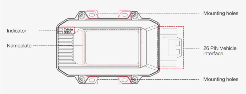
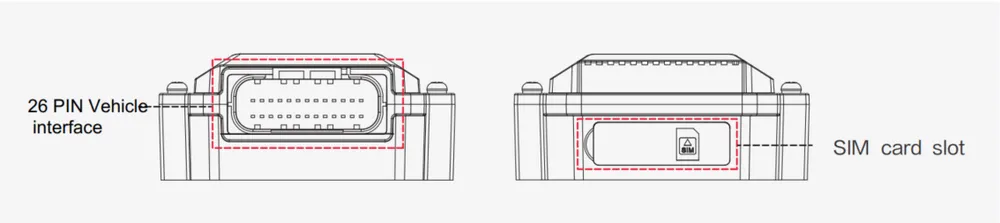
Fig. 1-2 VT310 Product Appearance
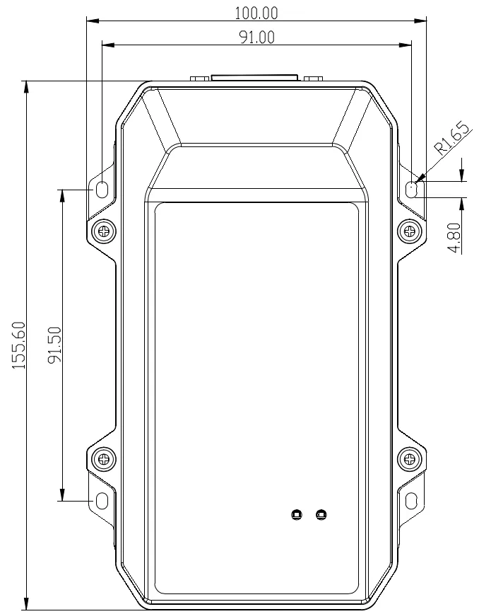
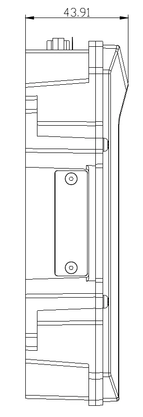
Fig. 1-3 VT320 Product Dimensions (Unit: mm)
1.4 SIM and Cable Installation
Install SIM Card: Open the waterproof baffle on the downside of the VT and insert the SIM card into the slot in the direction shown.
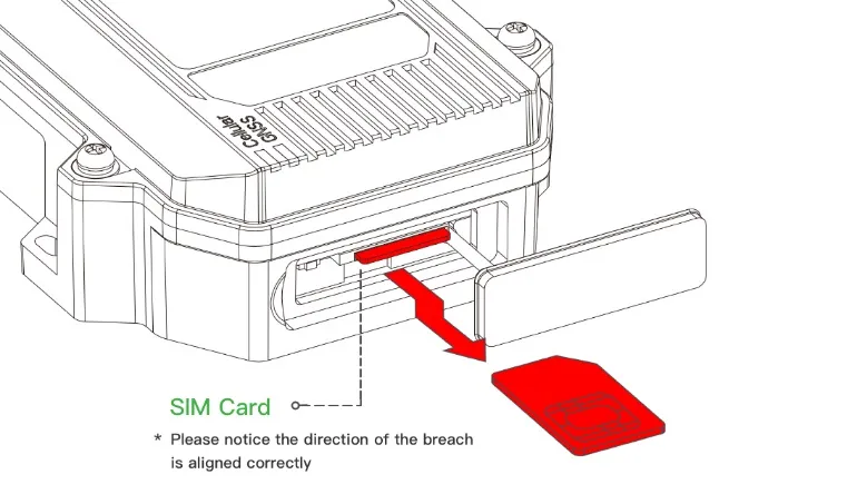
Fig. 1-4 Install SIM Card
Mount the Tracker: Fix the VT onto the vehicle with installation bolts. Recommended: under the front windshield for better GPS signal and easier OBD-II connection.
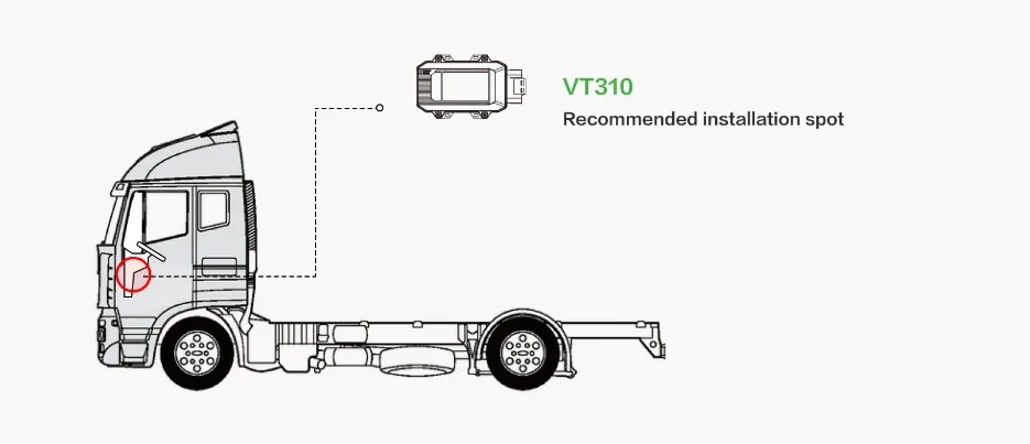
Fig. 1-5 Mount the Tracker
1.5 Cable Connection
VT310 26PIN All-in-one Test Cable
- Insert the 26PIN female head of P1 into the VT310.
- Connect P1 CONN-X-V- and P14 CONN-X-V+ to the negative and positive poles of the power adapter respectively. Connect P15 CONN-X-IGT and V+ both to the positive side of the power supply.
- Connect CONN-RS232-RX1, CONN-RS232-TX1 and GND to the TXD, RXD and GND of the DB9 or USB 232 connector, then connect to the computer.
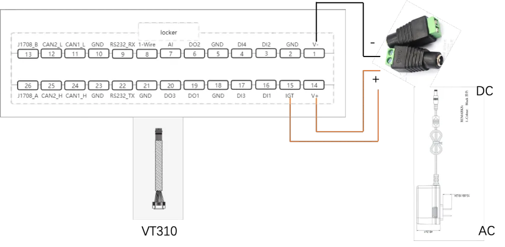
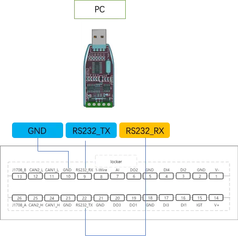
Fig. 1-6 VT310 26PIN Test Cable Connection
VT320 26PIN All-in-one Test Cable
- Insert the 26PIN female head of P1 into the VT320.
- Connect P2 VIN+ and VIN- to the positive and negative poles of the power adapter respectively. Connect IGT and VIN+ both to the positive side.
- Connect RS232-RX, RS232-TX and GND to the TXD, RXD and GND of the USB 232 connector.
1.6 26PIN Interface Definition
VT310 26PIN
| PIN | Name | PIN | Name | PIN | Name | PIN | Name |
|---|---|---|---|---|---|---|---|
| 1 | V- | 8 | 1-Wire | 14 | V+ | 21 | GND |
| 2 | GND | 9 | RS232_RX | 15 | IGT | 22 | RS232_TX |
| 3 | DI2 | 10 | GND | 16 | DI1 | 23 | GND |
| 4 | DI4 | 11 | CAN_1L | 17 | DI3 | 24 | CAN_1H |
| 5 | GND | 12 | CAN_2L | 18 | GND | 25 | CAN_2H |
| 6 | DO2 | 13 | J1708_B | 19 | DO1 | 26 | J1708_A |
| 7 | AI | 20 | DO3 |
VT320 26PIN
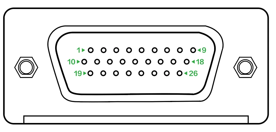
| PIN | Definition | Description |
|---|---|---|
| 1–4 | DI1–DI4 | Digital input; Status "1" 2.7–48 V / "0" 0–1 V |
| 6–8 | DO1–DO3 | Digital output; Status "0" 0–0.3 V / Hi-Z |
| 9 | 1WIRE | One Wire Bus |
| 10, 19 | VIN-, VIN+ | Power |
| 12 | AI | Analog input 0.5–48 V |
| 14–15 | J1708_B, J1708_A | J1708 bus |
| 16–18 | RS232_RX, RS232_TX, GND | Serial RS232 |
| 20 | IGT | Ignition signal |
| 22–26 | CAN1_H/L, CAN2_L/H | CAN bus |
1.7 Interface Details (RS232, DI, DO, AI, 1-Wire, IGT)
RS232: Used for debugging. Connect RS232_RX, RS232_TX, GND to TXD, RXD, GND of DB-9. Use RS232 to USB cable.
DI: Configurable pull-up. Default 10 kΩ pull-down to GND; 20 kΩ pull-up when enabled.
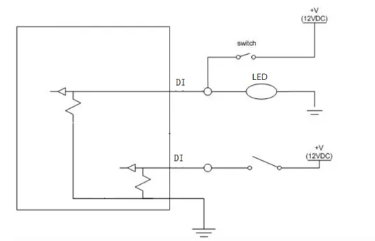
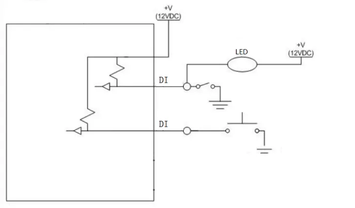
Fig. 1-7 DI Connection (No Pull-up / With Pull-up)
DO: Open-drain output, 300 mA max, usually works with relays.
AI: DC voltage detection. Input range 0.5–48 V; accuracy ±0.015 V; max operating current 2 μA.
1-Wire: Connect DQ to VT PIN 8 (VT310); VDD and GND to GND. Sensor type: DS18B20 (or less02b per original).
IGT: Connect to vehicle ignition switch. For office testing, connect IGT and V+ to DC power supply.
1.8 LED Indicators
GNSS Status Light
| Indicator Status | Function Status |
|---|---|
| Long off | Device not started or GNSS disabled |
| Flash (0.5 Hz) | GNSS time service succeeded; GNSS delivery successful |
| Slow flash (1 Hz) | GNSS function enabled |
| Solid | Location success |
Cellular Status Light
| Indicator Status | Function Status |
|---|---|
| Long off | Device disabled or dialup disabled |
| Flash (0.5 Hz) | Dialup succeeded |
| Slow flash (1 Hz) | Dialup enabled |
1.9 Restore Default Account and Password
When the device is restored to factory via hardware, only the username and password are restored to default. Press the Reset button with a screwdriver or other tool for more than 8 s, then release.
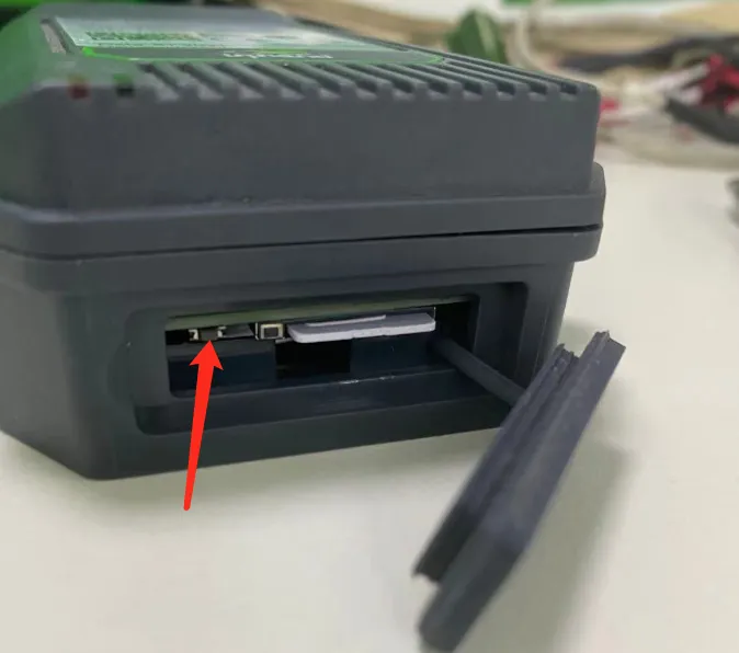
Fig. 1-8 Reset Button
Note: Double-clicking "Reset" can restart the device when it malfunctions.
1.10 Default Settings
| No. | Function | Default |
|---|---|---|
| 1 | Username/Password | admin / 123456 |
| 2 | Serial port baud rate | 115200 |
| 3 | Sleep voltage | 6 V |
| 4 | Wake-up interval | 120 min (0 = no sleep) |
| 5 | Wake-up time | 5 min |
2. Installation and First Use
2.1 Start the VT310/320
The device is under transportation mode in the factory state. The VT310/VT320 battery needs to be activated by external power supply or the vehicle diagnostic interface (VT320: open battery switch to activate).
2.2 Install Configuration Tool
The tool supports Windows 10 and Windows 11.
- Enter the InHand Download Center and download the configuration tool.
- Select the installation user and path. Click Install and wait until complete.
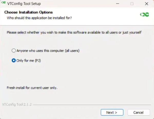
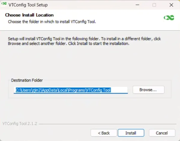
Fig. 2-1 Install Configuration Tool
2.3 Search COM Port and Login
- Power the VT with an external adapter through the 26PIN all-in-one test cable. Connect the VT to the computer through a USB to serial port cable. If the GNSS or cellular light flickers, the device has started successfully.
- In "Device Manager" >> "Ports (COM and LPT)", observe the COM port number.
- Open the VT config tool. If an error appears, open as administrator.
- Click "Connect" to connect to the serial port. Keep default username and password if unchanged. Ensure the serial port number is correct. Factory default baud rate: 115200 bps.
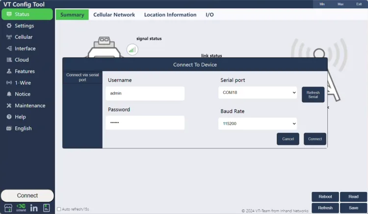
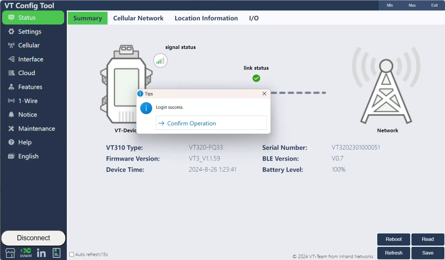
Fig. 2-2 Login
Login failed: Switch baud rate and reconnect. If username/password were changed, use the correct credentials.
3. Common Scenarios
3.1 Cellular Configuration
Goal: Configure the cellular network for data transmission.
Prerequisites: SIM card inserted, device powered on, config tool connected.
Est. time: ~5 min.
- Click "Cellular" to enter the configuration page.
- Configure "Network Access Point Name (APN)", "Network dialing user name", "Network dialing password", and "Authentication mode", then click "Save configuration". The device takes effect after restarting.
- For private-network cards, set APN (Access Point Name, can be understood as: the operator network's "address plate" that tells the device which entry to use for the mobile network) as required.
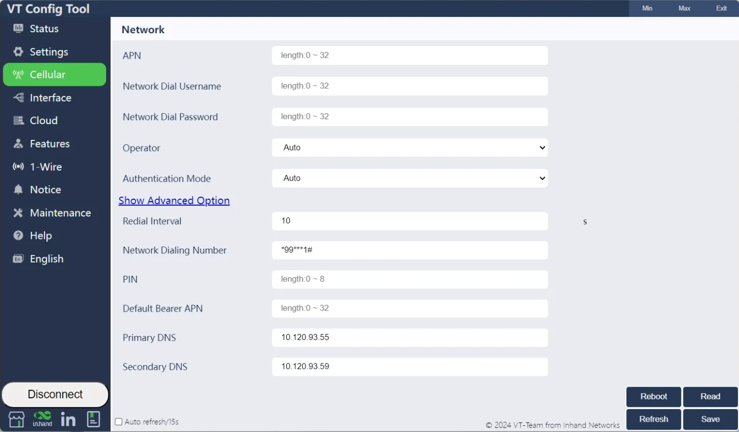
Fig. 3-1 Cellular Configuration
3.2 Cloud Platform Connection
Goal: Connect the VT310/320 to a cloud platform for data reporting.
Prerequisites: Cellular network connected, platform account created.
Est. time: ~10 min.
Supported platforms: SmartFleet, Azure IoT, Wialon, MQTT Broker, TCP/UDP Server, AWS IoT, Aliyun IoT, GEOTAB. The device can only connect to one cloud platform at a time.
SmartFleet: Domain, account, license plate number. Login: smartfleet.cloud.
Azure IoT: Connection string from Microsoft IoT platform.
Wialon: Domain name, port, reporting interval. Platform: hosting.wialon.com.
MQTT Broker: TLS1.2, username, password, domain, port, client ID, topic prefix.
AWS IoT: Port 8883; import certificate same as MQTT.
Aliyun IoT: Device Name, Region ID, Product Key, Device Secret or Product Secret; Unique-certificate-per-product or Unique-certificate-per-device.
GEOTAB: Geotab Username and Geotab Password from GEOTAB officials.
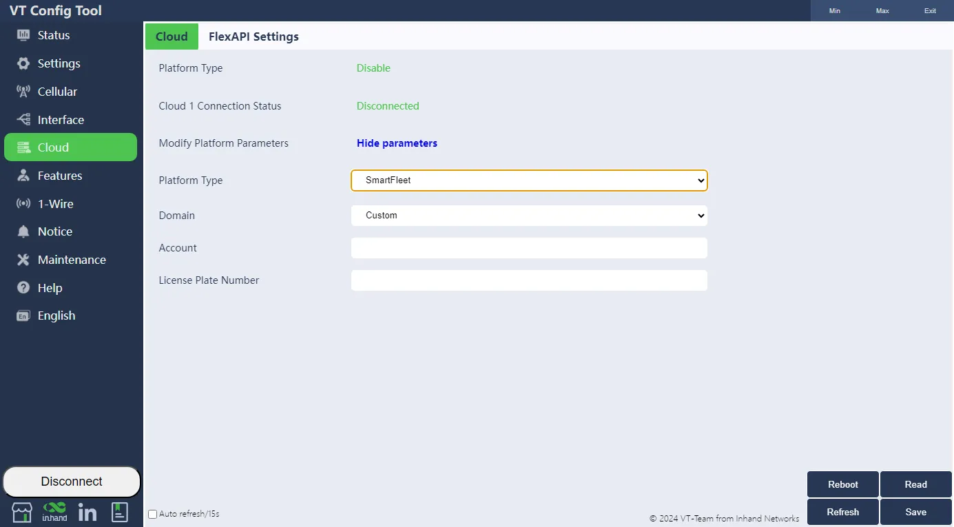
Fig. 3-2 Cloud Platform Selection
4. Function Reference
This section summarizes the main functions of the VT310/320. Full parameter tables and configuration details are in the original document.
4.1 Status
Includes Summary (model, serial number, firmware, Bluetooth, battery, network status), Mobile Network Parameters, Location Information, and I/O status.
Entry: Config tool >> Status
4.2 System Settings
Sleep Mode: Enable IGT, Wake-up interval (default 120 min; 0 = no sleep), Wake-up time (default 5 min), Sleep Delay. When device is in Temp run and sleep, light is off.
Account Settings: Change administrator username and password. Restart required after change.
Entry: Config tool >> System Settings
4.3 Cellular Network
Configure APN, network dialing username/password, authentication mode. Band configuration supported for VT310-FQ02 and VT200-FQ02.
Entry: Config tool >> Cellular
4.4 Interface (CAN, RS232, J1708, RS485, I/O)
CAN1/CAN2: Protocol type (J1939/J1979/Disable), Mode (Active/Passive/Silent), Baudrate (Default/250K/500K), Data Upload Format, Scan Interval, BLE Data Forward.
RS232: Function, baud rate, data bit, stop bit, parity bit.
J1708/RS485: VT300 series RS485 is multiplexed with J1708. Modbus acquisition: point table (slave address, function code, register address, query interval); max 20 configurations.
I/O: Configure DO high/low level, DI pull-up, input signal detection.
Entry: Config tool >> Interface
4.5 ELD (Electronic Logging Device)
When ELD is enabled, data from CAN, OBD and J1708 is forwarded as Bluetooth notification. Use Bluetooth LE Explorer (Microsoft Store) to connect; Bluetooth name is the same as SN.
Entry: Config tool >> Interface >> ELD
4.6 Cloud
Configure SmartFleet, Azure IoT, Wialon, MQTT Broker, TCP/UDP Server, AWS IoT, Aliyun IoT, GEOTAB, or Disable. FlexAPI settings: reserve group interval, custom group config import, GNSS upload interval.
Entry: Config tool >> Cloud
4.7 Features
Vehicle Status Detection: Max Cornering, Max Acceleration, Max Braking, Possible Accident Detection, IDLE Duration, Speed Monitoring. Configuration value is related to precision.
Entry: Config tool >> Features
4.8 1-Wire
View ROM ID, Device name, and current temperature of connected temperature/humidity sensor or iButton. Configure Data Upload Time and Temp Data Refresh Time.
Entry: Config tool >> 1-Wire
4.9 Notice
SMS Notice: Configure phone number and enable events to upload via SMS.
FlexAPI Notice: Enable events to upload to cloud platform.
Entry: Config tool >> Notice
4.10 Maintenance
Import/Export file: Export configuration to local JSON; import to device. Username and password are not included in export; add manually for import to new device.
Upgrade firmware: Select .IHD format file, click Upgrade, wait for completion. Restart after upgrade.
Entry: Config tool >> Maintenance
See also: 4.3 Cellular Network | 4.6 Cloud
5. Typical Applications
(Original document does not specify; to be supplemented)
Appendix A Troubleshooting
| Symptom | Possible Cause | Steps | Section |
|---|---|---|---|
| Cannot connect to config tool | Wrong COM port or baud rate | Check Device Manager for COM port; try 115200 bps | 2.3 Search COM Port and Login |
| Config tool error after install | Permission | Run as administrator | 2.2 Install Configuration Tool |
| Login failed | Wrong username/password or baud rate | Use correct credentials; switch baud rate and reconnect | 2.3 Search COM Port and Login |
| Cellular not connected | SIM, APN, authentication | 1. Check SIM insertion 2. Configure APN for private network 3. Set username/password and authentication mode |
3.1 Cellular Configuration |
| Cloud platform not linked | Wrong domain, port, credentials | Verify domain, port, account, or certificate per platform | 3.2 Cloud Platform Connection |
| Forgot admin password | — | Press Reset button >8 s to restore default | 1.9 Restore Default Account and Password |
| Device not started | Transportation mode | Activate by external power or vehicle diagnostic interface (VT320: open battery switch) | 2.1 Start the VT310/320 |
Appendix B Security Precautions
- Use the original or compatible power adapter (9–48 V for VT310, 12 V/2 A typical) to avoid damage.
- Do not install the device in strong electromagnetic interference environments.
- Ensure the operating environment meets the temperature and humidity requirements in the specification.
- Do not disassemble or modify the device; this may cause safety risks and void the warranty.
- Exported configuration files do not contain username and password; add them manually if importing to a new device with custom credentials.
Appendix C Get Device Log (CLI)
For users who need to obtain device logs via serial port. Connect the computer to the VT through USB to serial port, open a serial port tool (e.g., from Microsoft Store), select COM port, baud rate 115200/8/n/1. Character encoding: ASCII; Line break: \n (LF). Enter "+++" to activate CLI mode. Enter username and password to enter command line mode. Enter "log console enable" to enable logs; "log console disable" to disable. Enter "exit" to exit CLI mode (or wait 180 s for auto exit).
Note: Full descriptions of Sleep Mode state machine, CAN/J1708/RS485/Modbus parameters, OBD cable wiring, cloud platform configuration steps, certificate import, Features (Max Cornering, Acceleration, Braking, IDLE, Speed Monitoring), 1-Wire, Notice, Maintenance, and Help page, including screenshots, are in the original document.