Mo 62A Quick Start Guide
This document is for first-time Mo 62A users. It describes the shortest path from gathering parts to reaching the desktop or a remote login, and collects common reference material on board overview, cabling, networking, the camera, and the 40-pin header. The tone stays factual; procedural steps use second person for actions you can take.
On this page
| Section | Description |
|---|---|
| Shortest path to a working system | Read first: flash → cable → power → log in |
| Device overview | Positioning and key specifications |
| Board layout | Where interfaces sit on the board |
| What you need | Required and optional items |
| Flash the SD card | Image download and flashing on Windows |
| Hardware connections | Recommended cabling order |
| First boot | Boot time, default account, serial console |
| Network access | Ethernet, finding the IP, SSH, Wi-Fi |
| Camera preview (IMX219) | CSI wiring and preview script |
| 40-pin expansion header | Pinout, GPIO table, command examples |
| Common issues and tips | Black screen, camera, SD card, antenna |
Shortest path to a working system
To reach the desktop or SSH as quickly as possible, follow this order (details are in the sections below).
- Prepare: USB Type-C supply at 5 V and ≥ 3 A, Micro SD card ≥ 16 GB and Class 10 (or faster), downloaded
.img.zipimage, and optionally a Micro HDMI display and Ethernet cable. - Flash: On Windows, use balenaEtcher to write the image to the SD card; the operation erases all data on that card.
- Cable: Insert the SD card, display, Ethernet, and peripherals before applying power; non-essential items such as the camera can be connected later.
- Power: Connect USB-C last; the red LED should stay on to indicate power.
- Wait: The first boot spends about 1–2 minutes expanding the root filesystem and reboots once; afterward, expect about 30–45 seconds to the desktop.
- Log in: Username
debian, one-time default passwordtemppwd; the system requires an immediate password change after login. - Remote (optional): On the same LAN, use
ssh debian@<IP>orssh [email protected](mDNS required).
Device overview
About Mo 62A
Mo 62A is a single-board computer for edge AI inference, machine vision, industrial control, and similar scenarios. The SoC is TI AM62A7 (quad-core Arm Cortex-A53) with an on-die MMA (matrix multiply accelerator); peak AI inference performance is about 2 TOPS.
Key specifications
| Parameter | Specification |
|---|---|
| SoC | TI AM62A74 (quad-core Cortex-A53 @ 1.4 GHz + Cortex-R5F) |
| AI accelerator | MMA, 2 TOPS |
| Memory | LPDDR4 (32-bit) |
| Storage | Micro SD (boot / storage) |
| Display | Micro HDMI (up to 1080p, via SiI9022ACNU) |
| Networking | 1 × Gigabit Ethernet RJ45 |
| Wireless | Wi-Fi + Bluetooth (FG6221A, U.FL antenna) |
| USB | 1 × USB Type-C (power + USB 2.0), 4 × USB 2.0 Type-A |
| Camera | 22-pin FPC CSI (4-lane MIPI CSI-2) |
| Audio | 3.5 mm 4-pole headset jack |
| Expansion | 40-pin (GPIO / I2C / SPI / UART / PWM) |
| RTC | PCF85263ATL with coin-cell holder |
| Fan | PWM fan header (PWM + TACH) |
| Power | USB Type-C 5 V (≥ 3 A recommended) |
| LEDs | Red (power), green (activity) |
| Debug | UART0 console on 3-pin SH1.0 |
| Operating system | Debian 13 (Trixie) with XFCE |
Board layout
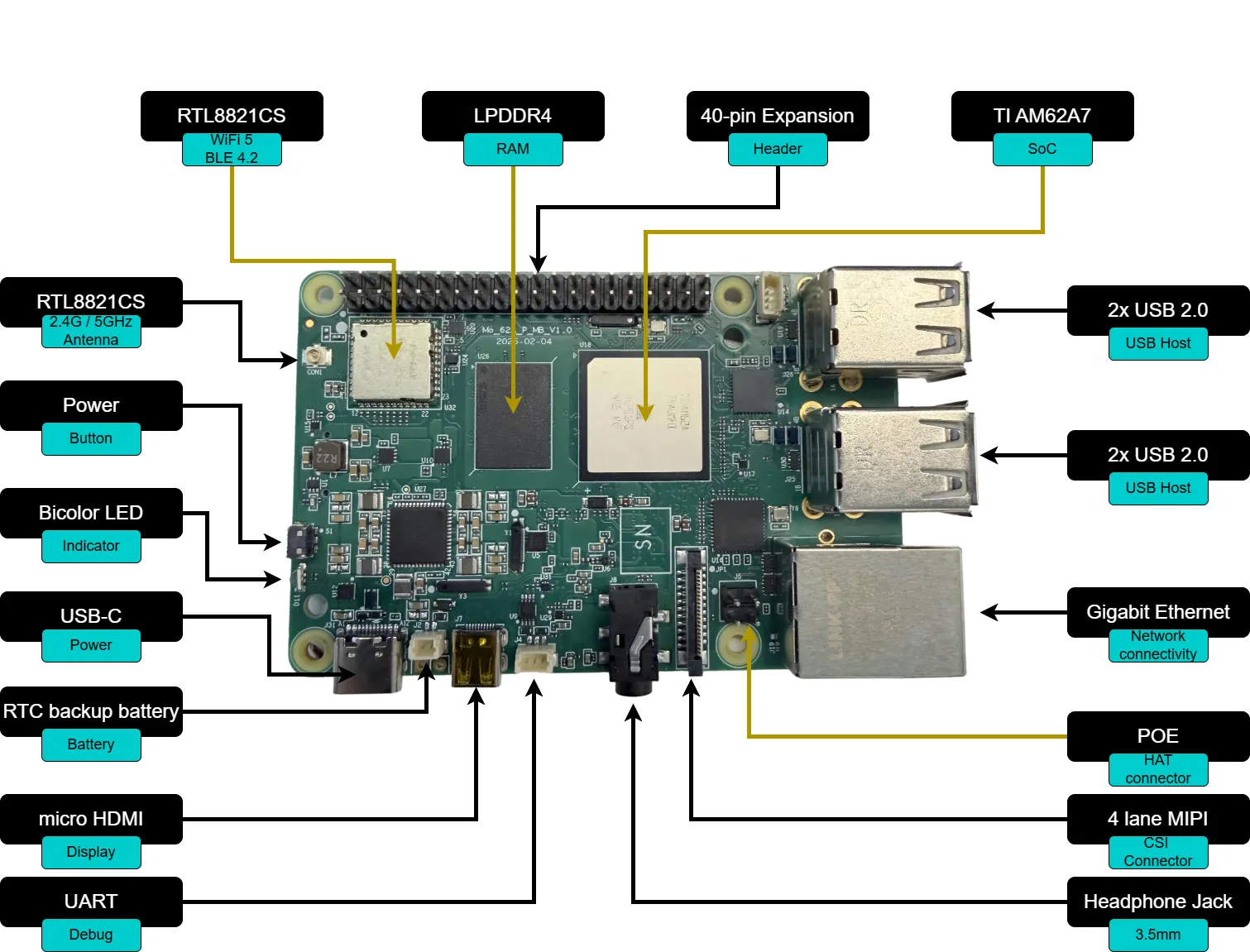
| Interface / component | Location |
|---|---|
| USB Type-C (power + USB 2.0) | Top edge, left |
| 4 × USB 2.0 Type-A | Top edge, right |
| Micro HDMI | Right side, upper |
| RJ45 Ethernet | Right side, lower |
| Micro SD slot | Bottom edge |
| 40-pin expansion header | Left edge |
| CSI camera connector | Center, FPC |
| 3.5 mm audio jack | Front edge |
| Wi-Fi / BT antenna (U.FL) | Near wireless module |
| Debug UART (SH1.0 3-pin) | Near USB-C |
| Fan connector | Near 40-pin header |
What you need
Required
| Item | Notes |
|---|---|
| Mo 62A board | — |
| USB Type-C power adapter | 5 V, ≥ 3 A |
| Micro SD card | ≥ 16 GB, Class 10 / UHS-I (U1) or faster |
| Micro HDMI cable | For a display or TV |
| RJ45 Ethernet cable | Initial wired network (find IP, SSH, etc.) |
| Host PC | Windows — for flashing the SD card |
Optional (by scenario)
| Item | Notes |
|---|---|
| IMX219 CSI camera module | Required for CSI preview |
| USB keyboard and mouse | Local XFCE use |
| 3.5 mm headset | Headphone output + microphone input |
| CR1220 coin cell | RTC backup |
| Wi-Fi antenna (U.FL) | Much better wireless range |
| PWM fan | 4-pin, 5 V |
Flash the SD card
Download the image
Download the latest pre-built SD card image from the releases page; it is distributed as .img.zip.
Full SDK source (kernel, device tree, filesystem customization) repository:
GitHub: https://github.com/inhandnet/mo-62a
Flash with balenaEtcher (Windows)
- Install balenaEtcher.
- Click Flash from file.
- Select the downloaded
.img.zipfile. - Click Select target.
- Choose the Micro SD card from the device list.
- Click Flash! to start writing.
- When Flash Complete! appears, eject the card safely in the OS before removing it.
Warning: Flashing erases all existing data on the SD card.
Hardware connections
Use this order to reduce the risk of hot-plugging (camera details are under Camera preview (IMX219)).
- Insert the SD card: Push the card into the underside slot until it clicks.
- Connect the display: Run Micro HDMI from the board to the monitor.
- Connect Ethernet: Plug RJ45 into the Gigabit port if you plan to use wired networking.
- Connect peripherals: Attach keyboard, mouse, or other devices to any USB 2.0 Type-A port (optional).
- Connect the camera: For IMX219, route the FPC to the 22-pin CSI connector (see “Connect the camera” below).
- Apply power: Connect the USB Type-C supply last; the red power LED should light.
First boot
Boot sequence
After power-on, the system boots from Micro SD. A typical cold boot takes about 30–45 seconds; the green activity LED blinks during boot.
First boot note: On the first power-on the root filesystem expands to use the remaining SD space, which takes about 1–2 minutes and ends with an automatic reboot. The XFCE desktop appears after that second boot completes. Later boots match the typical time above.
Typical boot chain:
- U-Boot SPL (R5) → U-Boot (A53) — short console output on the serial port
- Linux kernel decompresses and loads the device tree
- systemd brings up services — first boot runs expansion here and triggers the reboot
- XFCE desktop on HDMI
Desktop login
XFCE starts automatically. Default local account:
| Field | Value |
|---|---|
| Username | debian |
| Password | temppwd |
The default password is one-time use; after login the system forces a new password, which takes effect immediately.
Serial console (UART0)
Without a display, use the 3-pin UART0 header (SH1.0, 1.0 mm pitch) with a USB serial adapter or similar.
| Pin | Signal |
|---|---|
| 1 | RXD |
| 2 | TXD |
| 3 | GND |
Settings: 115200 8N1, no flow control.
Network access
Wired Ethernet
After boot, eth0 uses DHCP for IPv4 by default.
Find the board IP
On the board:
If the LAN supports mDNS, you can try:
SSH login
|
Wi-Fi
On the command line you can use nmcli:
You can also use the graphical network applet in the XFCE tray.
The on-board connector is U.FL; an external antenna usually improves Wi-Fi range and stability a lot.
Camera preview (IMX219)
The 22-pin FPC CSI port works with an IMX219 CSI sensor module.
Connect the camera
- Flip up the CSI connector latch.
- Insert the FPC with the contacts facing the board (metal pads down).
- Press the latch closed.
Run the preview
The image includes /usr/local/bin/imx219-preview.sh.
Video goes to HDMI; press Ctrl+C in the terminal to stop.
The script needs
sudobecausekmssinkrequires DRM master. It pauses the desktop session (lightdm) while running and usually restores it afterward.
Tunable environment variables
| Variable | Default | Range | Description |
|---|---|---|---|
FPS (1st argument) |
15 |
5/8/10/15/30 | Frame rate |
WB_R |
0.5 |
0.0 – 1.0 | White balance red reference |
WB_B |
0.6 |
0.0 – 1.0 | White balance blue reference |
GAIN |
150 |
0 – 232 | Analog gain |
DGAIN |
256 |
256 – 4095 | Digital gain |
EXPOSURE |
auto | lines | Exposure in lines |
Warmer example at 10 fps:
40-pin expansion header
The 40-pin header defaults to GPIO mode at 3.3 V logic. I2C, SPI, UART, PWM, and other functions can be enabled with a device tree overlay.
Pins 27 and 28 (I2C2) are fixed for the camera module I2C bus and are not suited as general GPIO.
Pin map
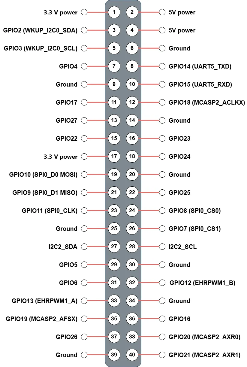
See the numbered table below.
Linux GPIO reference
Use gpioset / gpioget from the gpiod package for GPIO-mode pins.
| Pin | Name | Default function | gpiochip | Line | Alternate function |
|---|---|---|---|---|---|
| 1 | 3V3 | 3.3 V power | — | — | — |
| 2 | 5V | 5 V power | — | — | — |
| 3 | GPIO2 | GPIO (MCU_GPIO0_20) | gpiochip0 | 20 | WKUP_I2C0_SDA |
| 4 | 5V | 5 V power | — | — | — |
| 5 | GPIO3 | GPIO (MCU_GPIO0_19) | gpiochip0 | 19 | WKUP_I2C0_SCL |
| 6 | GND | Ground | — | — | — |
| 7 | GPIO4 | GPIO (GPIO0_39) | gpiochip1 | 39 | — |
| 8 | GPIO14 | GPIO (GPIO1_25) | gpiochip2 | 25 | UART5_TXD |
| 9 | GND | Ground | — | — | — |
| 10 | GPIO15 | GPIO (GPIO1_24) | gpiochip2 | 24 | UART5_RXD |
| 11 | GPIO23 | GPIO (GPIO1_23) | gpiochip2 | 23 | — |
| 12 | GPIO18 | GPIO (GPIO1_0) | gpiochip2 | 0 | MCASP2_ACLKX |
| 13 | GPIO27 | GPIO (GPIO0_42) | gpiochip1 | 42 | — |
| 14 | GND | Ground | — | — | — |
| 15 | GPIO22 | GPIO (GPIO1_22) | gpiochip2 | 22 | — |
| 16 | GPIO17 | GPIO (GPIO0_38) | gpiochip1 | 38 | — |
| 17 | 3V3 | 3.3 V power | — | — | — |
| 18 | GPIO24 | GPIO (GPIO0_40) | gpiochip1 | 40 | — |
| 19 | GPIO10 | GPIO (GPIO1_18) | gpiochip2 | 18 | SPI0_D0 (MOSI) |
| 20 | GND | Ground | — | — | — |
| 21 | GPIO9 | GPIO (GPIO1_19) | gpiochip2 | 19 | SPI0_D1 (MISO) |
| 22 | GPIO25 | GPIO (GPIO0_14) | gpiochip1 | 14 | — |
| 23 | GPIO11 | GPIO (GPIO1_17) | gpiochip2 | 17 | SPI0_CLK |
| 24 | GPIO8 | GPIO (GPIO1_15) | gpiochip2 | 15 | SPI0_CS0 |
| 25 | GND | Ground | — | — | — |
| 26 | GPIO7 | GPIO (GPIO1_16) | gpiochip2 | 16 | SPI0_CS1 |
| 27 | I2C2_SDA | I2C2 SDA (i2c-2) |
— | — | (camera bus, fixed) |
| 28 | I2C2_SCL | I2C2 SCL (i2c-2) |
— | — | (camera bus, fixed) |
| 29 | GPIO5 | GPIO (GPIO0_36) | gpiochip1 | 36 | — |
| 30 | GND | Ground | — | — | — |
| 31 | GPIO6 | GPIO (GPIO0_33) | gpiochip1 | 33 | — |
| 32 | GPIO12 | GPIO (GPIO1_14) | gpiochip2 | 14 | EHRPWM0_B |
| 33 | GPIO13 | GPIO (GPIO1_13) | gpiochip2 | 13 | EHRPWM0_A |
| 34 | GND | Ground | — | — | — |
| 35 | GPIO19 | GPIO (GPIO0_91) | gpiochip1 | 91 | MCASP2_AFSX |
| 36 | GPIO16 | GPIO (GPIO1_9) | gpiochip2 | 9 | EHRPWM1_A |
| 37 | GPIO26 | GPIO (GPIO0_41) | gpiochip1 | 41 | — |
| 38 | GPIO20 | GPIO (GPIO1_5) | gpiochip2 | 5 | MCASP2_AXR0 |
| 39 | GND | Ground | — | — | — |
| 40 | GPIO21 | GPIO (GPIO1_2) | gpiochip2 | 2 | MCASP2_AXR1 |
gpiochip0=mcu_gpio0(MCU domain);gpiochip1=main_gpio0(GPIO0_x);gpiochip2=main_gpio1(GPIO1_x).
Voltage levels and protection
Expansion I/O is 3.3 V. Do not connect 5 V logic directly to GPIO pins.
Command examples (libgpiod v2)
The image includes libgpiod 2.x; use -c to select a controller.
List controllers:
Read an input (example: physical pin 11 → gpiochip2 line 23):
Read several lines:
Drive high (example: pin 7 → gpiochip1 line 39):
Timed drive:
Square wave (500 ms high / 500 ms low):
Edge monitor:
Scan I2C2 (/dev/i2c-2):
PWM (pin 32 → pwmchip0 channel 0, 1 kHz, 50% duty):
Common issues and tips
No display after boot
The image disables DPMS by default. Press a key or move the mouse to rule out idle blanking. If there is still no picture, on the board run:
Camera not detected
If the expected device is missing, check that the FPC is fully inserted and the latch is closed.
SD card not found during boot
- Confirm the card clicked fully into the slot.
- Try another card: capacities that are too small or speeds below Class 10 may be unreliable.
- Reflash and confirm Etcher reported no errors.
Wi-Fi antenna
Without an external antenna on the U.FL port, usable range is usually very small; install a matching antenna for stable Wi-Fi.