InPAD070S/3101 User Manual
Declaration
Thank you for choosing InHand Networks products. Before use, read this user manual carefully. Compliance with the following declarations helps maintain intellectual property rights and legal compliance, and ensures the usage experience remains consistent with the latest product information. For any questions or to obtain written permission, contact the technical support team.
- Copyright Notice
This user manual contains copyrighted material. Copyright belongs to InHand Networks Technology Co., Ltd. and its licensors. Without written permission, no unit or individual may excerpt, reproduce, or distribute any part or all of the contents of this manual in any form.
- Disclaimer
Due to continuous product technology and specification updates, the company cannot guarantee that the information in this user manual is completely identical to the actual product. Therefore, the company assumes no liability for any disputes arising from discrepancies between actual technical parameters and the user manual. Any product changes are subject to final change and interpretation rights reserved by the company without prior notice.
- Copyright Information
The contents of this user manual are protected by copyright law. Copyright belongs to InHand Networks Technology Co., Ltd. and its licensors. All rights reserved. Without written permission, no one may use, reproduce, or distribute the contents of this manual.
Conventions
Symbol Conventions
The following symbols are used throughout this manual:
| Symbol | Meaning | Example |
|---|---|---|
< > |
Indicates a variable or parameter to be replaced with an actual value | <IP Address> indicates a specific IP address must be entered |
" " |
Indicates text labels on the interface | Click the "Save" button |
→ |
Indicates menu hierarchy or operation sequence | Settings → Display |
【 】 |
Indicates a menu or page name | Enter the 【System Settings】page |
Command Line Format Conventions
| Format | Significance |
|---|---|
| Bold | Command keywords (the part that should remain unchanged in a command and be entered as-is) |
| Italic | Command parameters (the part that must be replaced with the actual value in a command) |
[ ] |
Indicates that the part in "[ ]" is optional in command configuration |
{ x / y / ... } |
Indicates to select one from multiple options |
[ x / y / ... ] |
Indicates to select one or not to select from multiple options |
{ x / y / ... } * |
Indicates to select at least one from multiple options |
[ x / y / ... ] * |
Indicates to select one or more or not to select from multiple options |
Warning Signs
| Sign | Meaning |
|---|---|
 |
Provides necessary complement or description on the contents of operation |
Note: Improper operation may cause data loss or damage to the device.
Technical Support
Email: [email protected]
URL: www.inhand.com
How to Use This Manual
Read by User Type
- First-time users: Read in sequence through Device Overview → Installation and First Use → Common Scenario Configuration → Function Description and Parameter Reference
- Existing device users: Refer directly to Function Description and Parameter Reference or Appendix Troubleshooting
- Developer users: Refer to Developer Options and Serial Port Test in Function Description and Parameter Reference
Quick Task Reference
| Task | Corresponding Chapter | Estimated Time |
|---|---|---|
| Install and power on the device | Installation and First Use | ~10 minutes |
| Connect to cellular network | Scenario 1: Cellular Network Access | ~5 minutes |
| Connect to Wi-Fi network | Scenario 2: Wi-Fi Connection | ~5 minutes |
| Configure Ethernet | Scenario 3: Ethernet Configuration | ~5 minutes |
| Adjust display settings | Scenario 4: Display Settings | ~5 minutes |
| Upgrade system firmware | Scenario 5: System Upgrade | ~10 minutes |
| Install third-party applications | Scenario 6: Application Installation | ~5 minutes |
| Troubleshoot device issues | Appendix A: Troubleshooting | As needed |
Chapter 1: Device Overview
1.1 Overview
The InPAD series is a new generation of 4G smart terminal products designed for smart business applications. Powered by the RK3288 processor, the device supports multiple connectivity options including 3G/4G cellular, Wi-Fi, and wired Ethernet, providing uninterrupted and stable internet access. The InPAD series enables customers to collect and organize local data, upload data in real time to third-party cloud management platforms, and realize remote monitoring and management functions. The InPAD070S provides higher performance, lower power consumption, and a more stable hardware and software environment, ensuring fast and reliable data transmission.
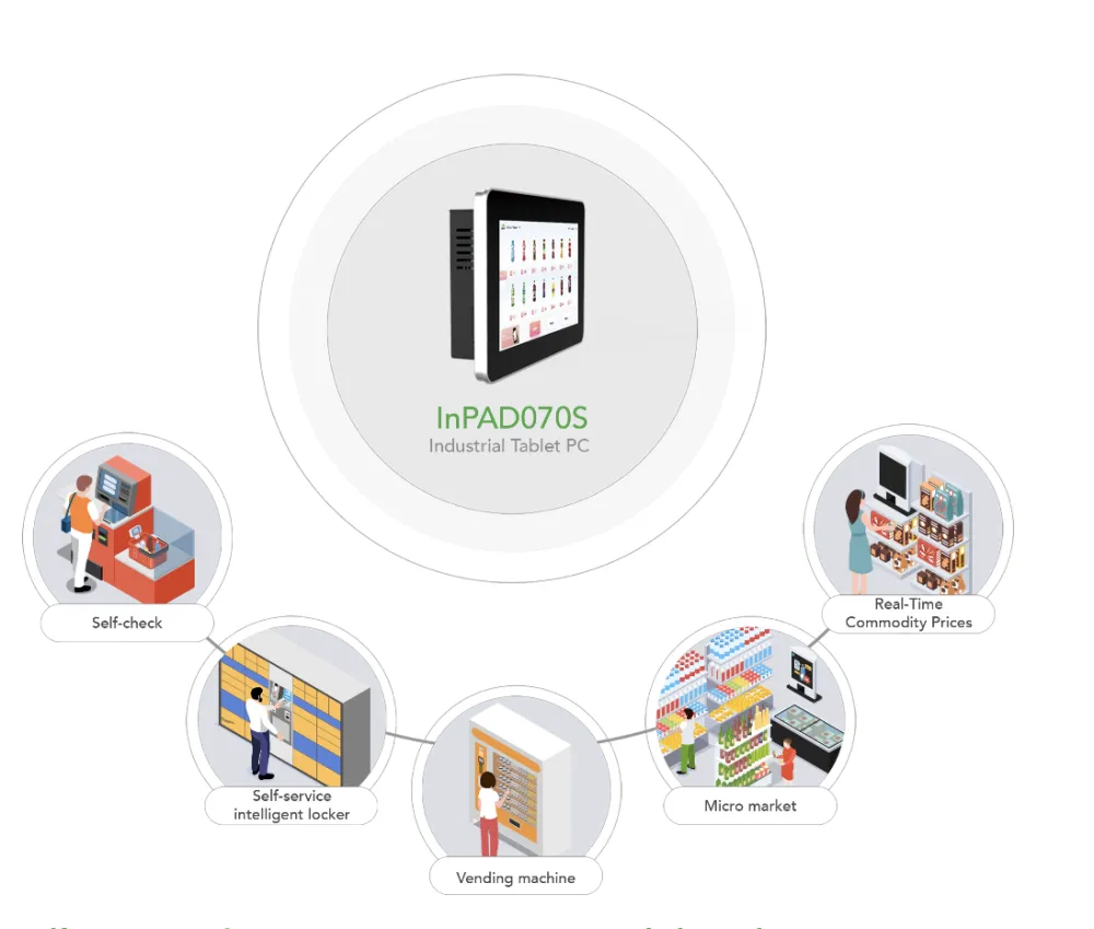
Figure 1-1 Application Diagram
1.2 Packing List
Note: Due to differences in product models and accessory selections, the following items may or may not be included in the package.
| Item | Quantity | Description |
|---|---|---|
| InPAD | 1 | InPAD series product |
| RS485 terminal | 1 | 5-pin industrial green terminal |
| RS232 terminal | 2 | 3-pin industrial green terminal |
| Product warranty card | 1 | Warranty period: 1 year |
| Antenna (Optional) | 1 | 3G/4G Antenna |
| Antenna (Optional) | 1 | Wi-Fi Antenna |
| AC power cord (Optional) | 1 | Power cord for American, English, Australian or European Standard |
| Power Adapter (Optional) | 1 | 12VDC Power Adapter |
1.3 Appearance and Interfaces
1.3.1 Front Panel
The front panel of this series features a high-brightness capacitive touch screen, supporting 7 inches (1024 x 600) and 10.1 inches (1280 x 800). The dustproof and waterproof rating of the screen is IP65.
Figure 1-2 Front Panel
1.3.2 Rear Panel
The rear panel of the InPAD070S product has two types of mounting holes:
- 4 VESA mounting holes (75 x 75 mm). VESA mounting screws: M4 x 8 screws, screw depth: 8 mm (maximum)
- 4 mounting holes for hanging or fixed mounting components. Mounting screws: M3 x 6 screws.
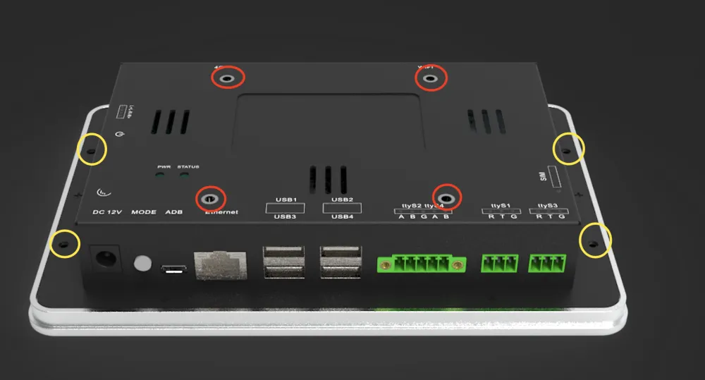
Figure 1-3 Rear Panel
1.3.3 Equipment Interface
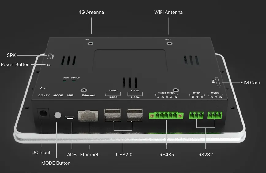
Figure 1-4 Rear Interface
This series is mainly divided into two types of equipment: InPAD070S and InPAD3101. The peripheral interfaces of the equipment are as follows:
| Interface | InPAD070S | InPAD3101 |
|---|---|---|
| Display | 7-inch display, Resolution: 1024 x 600 | 10.1-inch display, Resolution: 1280 x 800 |
| Button | PWR x 1, MODE x 1 | PWR x 1, MODE x 1 |
| Power interface | Power input: DC-input, 12V, circular interface (5521) | Power input: DC-input, 12V, circular interface (5521) |
| SIM Card | SIM card slot x 1 | SIM card slot x 1 |
| USB | USB 2.0 x 4 | USB 2.0 x 4 |
| RS485 | RS485 serial port x 2, 5-pin industrial terminal, pitch 3.5 mm, with flange [ttyS2, ttyS4] | RS485 serial port x 2, 5-pin industrial terminal, pitch 3.5 mm, with flange [ttyS2, ttyS4] |
| RS232 | RS232 serial port x 2, 3-pin industrial terminal, spacing 3.5 mm, no flange | RS232 serial port x 2, 3-pin industrial terminal, spacing 3.5 mm, no flange |
| Network port | 10/100 Mbps x 1, WAN/LAN | 10/100 Mbps x 1, WAN/LAN |
| Antenna interface | Wi-Fi x 1, 4G x 1 | Wi-Fi x 1, 4G x 1 |
| Debug interface | Micro USB x 1 | Micro USB x 1 |
| Bluetooth | 4.2 | 4.2 |
1.3.3.1 RS485 Interface Definition
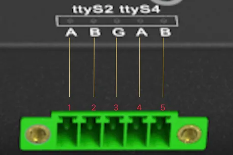
Figure 1-5 RS485 Interface Definition
| Pin | Definition |
|---|---|
| 1 | RS-485 Signal A (ttyS2) |
| 2 | RS-485 Signal B (ttyS2) |
| 3 | GND |
| 4 | RS-485 Signal A (ttyS4) |
| 5 | RS-485 Signal B (ttyS4) |
1.3.3.2 RS232 Interface Definition
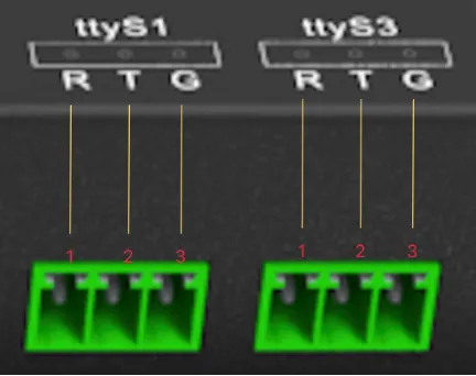
Figure 1-6 RS232 Interface Definition
| Pin | Definition |
|---|---|
| 1 | RS-232 RxD |
| 2 | RS-232 TxD |
| 3 | RS-232 GND |
1.4 LED Indicators
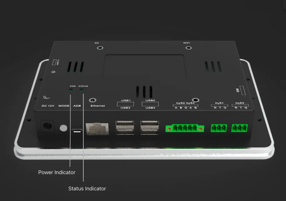
Figure 1-7 LED Indicator Location
| Indicator | Status | Meaning |
|---|---|---|
| Power Indicator | Steady on | Device is powered on |
| Status Indicator | Blinking | Device is operating normally |
1.5 Factory Reset
If the current system is Android 7.1:
- Navigate to Settings → Backup \& reset → Factory data reset → RESET TABLET.
- Confirm the reset operation.
If the current system is Android 12:
- Navigate to Settings → System → Reset options → Erase all data → RESET TABLET.
- Confirm the reset operation.
Warning: Use this function with caution. After factory reset, all data on the product will be cleared.
1.6 Default Settings
| Parameter | Default Value |
|---|---|
| LAN IP Address | 192.168.1.100 |
| LAN Subnet Mask | 255.255.255.0 |
| Ethernet Mode | Disabled by default |
| Wi-Fi | Disabled by default |
| 4G/Cellular | Disabled by default |
| ICMP Detection | Enabled by default |
| Developer Options | Disabled by default |
| USB Debugging | Disabled by default |
1.7 Dimensions
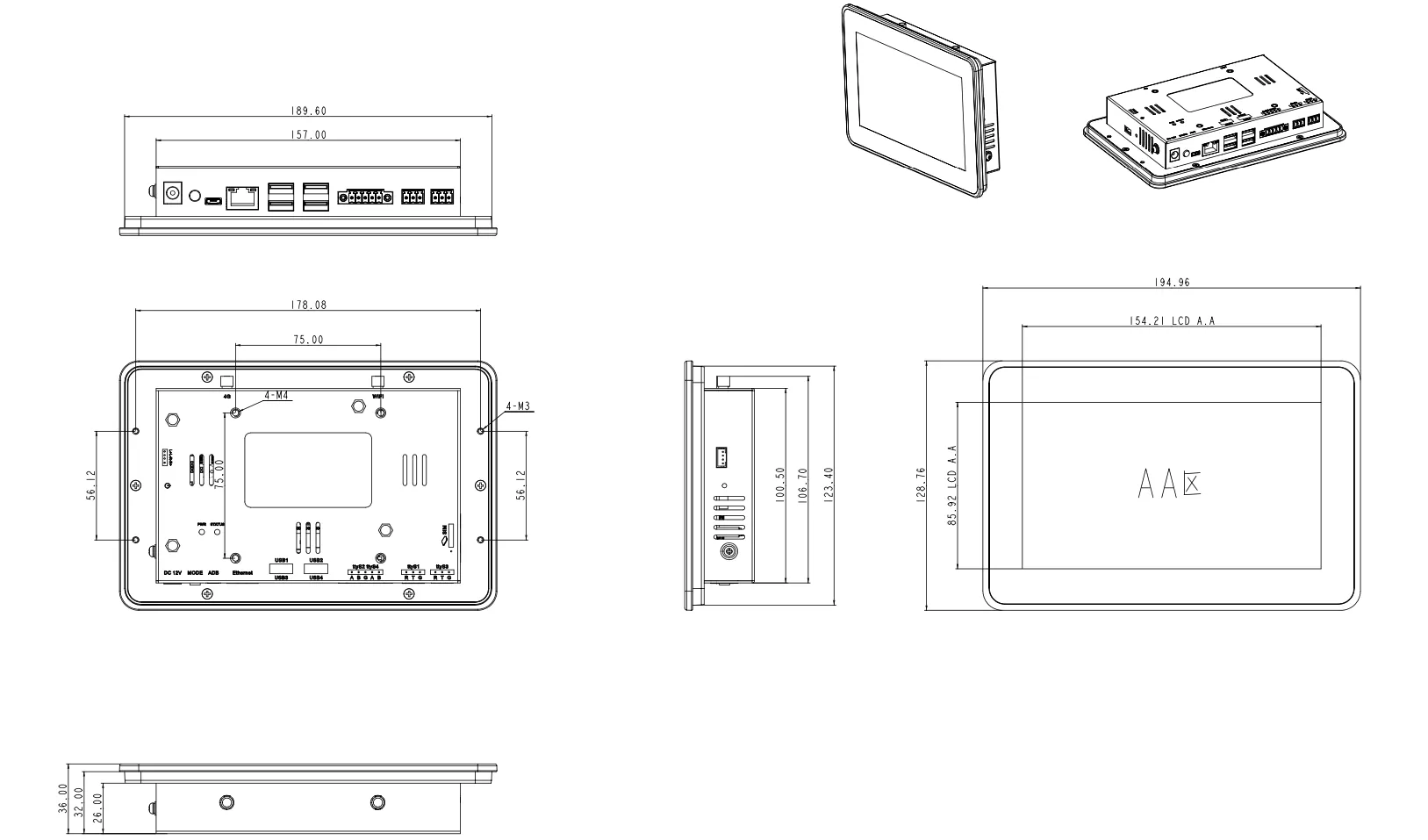
Figure 1-8 InPAD070S Dimensions
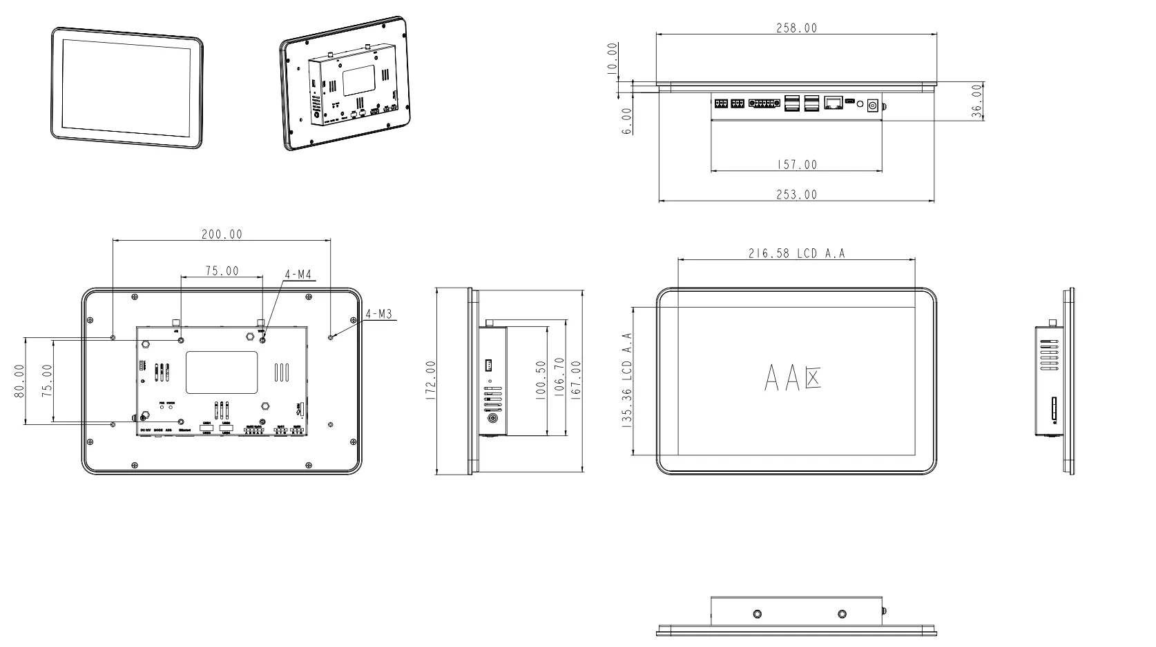
Figure 1-9 InPAD3101 Dimensions
Chapter 2: Installation and First Use
2.1 Pre-Installation Preparation
2.1.1 Environment Requirements
| Item | Specification |
|---|---|
| Power supply | 12 V DC |
| Operating temperature | -10°C to 60°C |
| Storage temperature | -40°C to 85°C |
| Relative humidity | 5% to 95% (non-condensing) |
2.1.2 Tools and Accessories Required
- Mounting screws (M3 x 6 or M4 x 8, depending on mounting method)
- Grounding cable (depending on installation environment)
- Appropriate mounting brackets or sheet metal parts
- SIM card (for cellular network use)
- Cellular antenna (for cellular network use)
- Wi-Fi antenna (for Wi-Fi use)
2.1.3 Safety Precautions
Warning: Before installation, verify that the power supply voltage matches the device specification (12 V DC). Incorrect voltage may damage the device.
Caution: Keep the device out of direct sunlight, away from heat sources or areas with strong electromagnetic interference.
Caution: Verify that all required cables and connectors are available before starting installation.
2.2 Installation Guide
Note: This series of products is not equipped with mounting parts by default. Select appropriate mounting parts according to the installation environment.
2.2.1 M3 Hole Installation
- Find a suitable installation position on the machine, reserving sufficient space for wiring operations.
- Select the appropriate installation method according to the mounting parts, and fix the sheet metal parts to the back of the device and the installation panel through the screw holes.
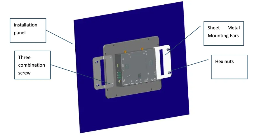
Figure 2-1 Sheet Metal Mounting Ear Installation
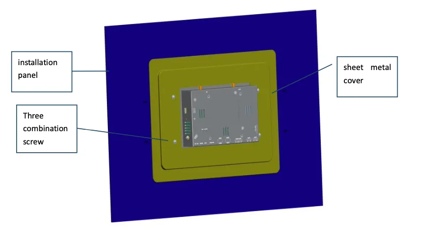
Figure 2-2 Sheet Metal Cover Installation
2.2.2 VESA Standard Hole Installation
- Find a suitable installation position on the machine, reserving sufficient space for wiring operations.
- Select the appropriate installation method according to the mounting parts, and fix the sheet metal parts to the back of the device and the installation panel through the VESA screw holes (75 x 75 mm).
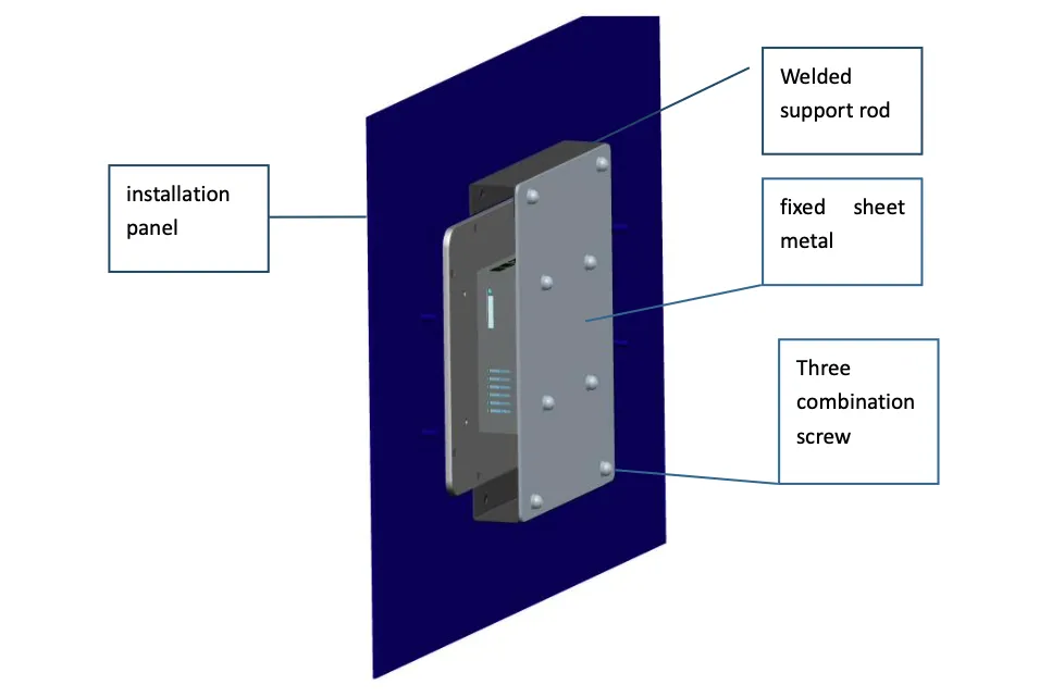
Figure 2-3 Fixed Sheet Metal Installation
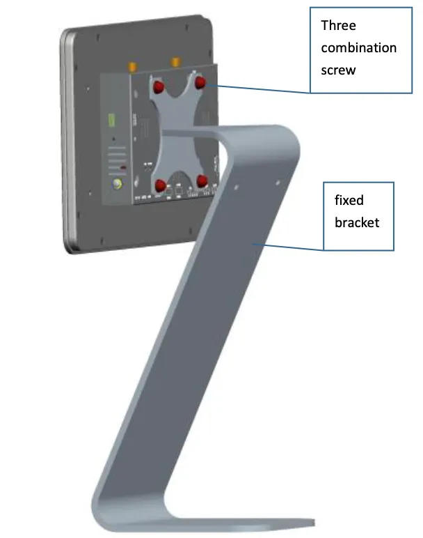
Figure 2-4 Fixed Bracket Installation
2.3 Ground Protection
- Loosen the ground nut.
- Put the grounding ring of the cabinet grounding cable on the grounding post.
- Tighten the ground nut.
Note: Ground the device to improve its immunity to interference. Depending on the environment of use, connect the ground wire to the grounding post of the device.
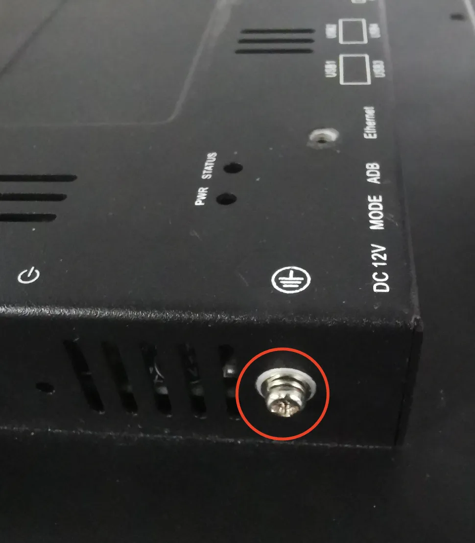
Figure 2-5 Ground Protection Installation
2.4 Power Connection
- Connect the 12 V DC power adapter to the circular power interface (5521) on the device.
- Connect the power cord to a suitable power outlet.
- Verify that the power indicator lights up steadily after power-on.
2.5 First Power-On
- After connecting power, the device will start automatically.
- Wait for the system to complete booting (status indicator blinking indicates normal operation).
- The Android desktop will appear on the touch screen.
2.6 Quick Check
After installation is complete, verify the following items:
- Device is securely mounted and all screws are tightened
- Ground connection is properly secured (if applicable)
- Power indicator is steady on after power-on
- Status indicator is blinking during normal operation
- Touch screen responds to touch input
- Android desktop is displayed correctly
- All required antennas are connected (if using Wi-Fi or cellular)
- SIM card is properly inserted (if using cellular network)
Chapter 3: Common Scenario Configuration
Scenario 1: Cellular Network Access
Objective: Access the internet through 4G cellular network.
Prerequisites: SIM card is inserted and cellular antenna is installed. Device is powered on.
Estimated Time: ~5 minutes.
Operation Steps: 1. Insert the SIM card into the SIM card slot. 2. Install the 4G cellular antenna. 3. If the current system is Android 7.1: Navigate to Settings → More → Cellular networks → Access Point Names. If the current system is Android 12: Navigate to Settings → Network \& internet → SIMs → Access Point Names. 4. Click the add symbol in the upper right corner. 5. Fill in the Name and APN (APN parameters must be obtained from the carrier). 6. Click the save symbol in the upper right corner. 7. In the APN list, select the newly added APN.
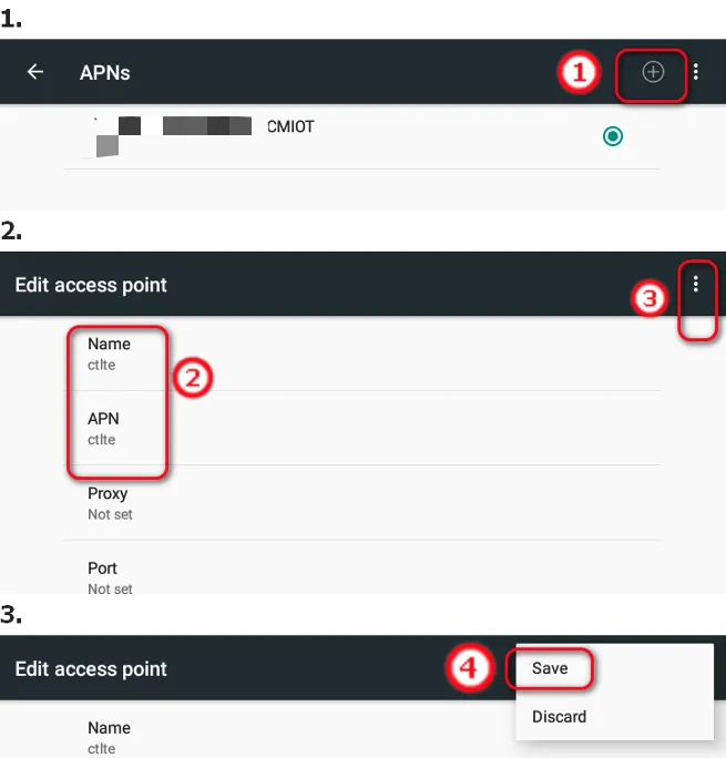
Figure 3-1 APN Settings
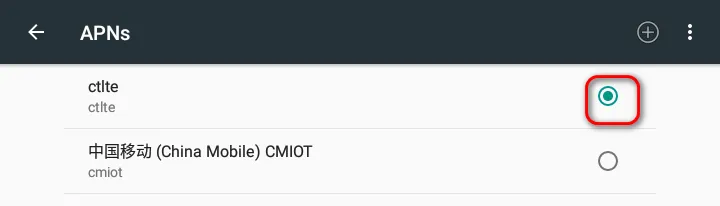
Figure 3-2 APN List Selection
Verification Method: 1. Check the cellular signal icon in the status bar. 2. Open a web browser and access an internet website to confirm connectivity.
Common Issues: - Network connection failure: Verify the SIM card is correctly inserted and the APN parameters match the carrier requirements. - Weak signal or no signal: Check whether the cellular antenna is connected and adjust the device position.
Scenario 2: Wi-Fi Connection
Objective: Connect the device to an existing Wi-Fi network.
Prerequisites: Wi-Fi antenna is connected. A Wi-Fi network is available within range.
Estimated Time: ~5 minutes.
Operation Steps:
- Ensure the Wi-Fi antenna is connected before enabling the WLAN interface.

Figure 3-3 Wi-Fi Antenna Warning
- If the current system is Android 7.1: Navigate to Settings → Wi-Fi. If the current system is Android 12: Navigate to Settings → Network \& internet → Internet → Wi-Fi.
- Click the switch symbol in the upper right corner to turn on Wi-Fi.
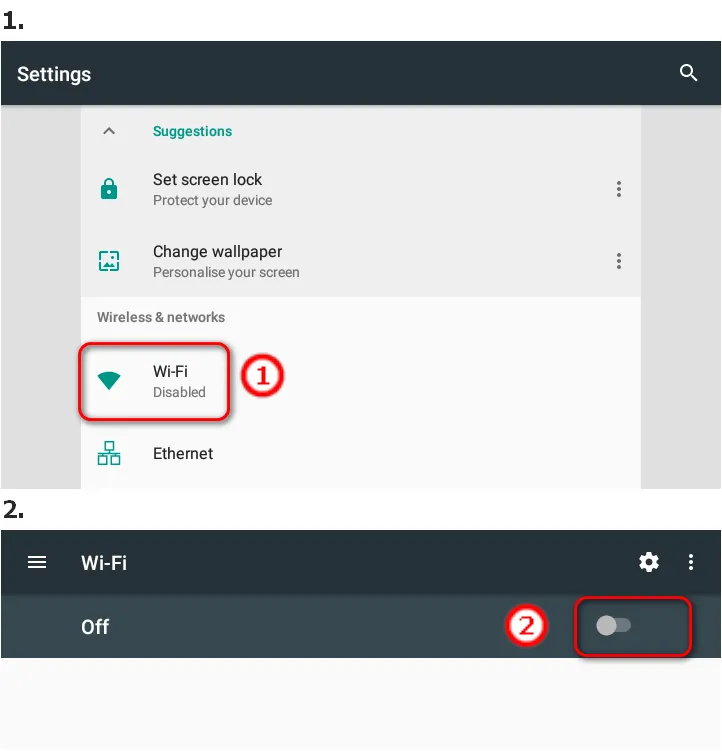
Figure 3-4 Wi-Fi Settings (Android 7.1)
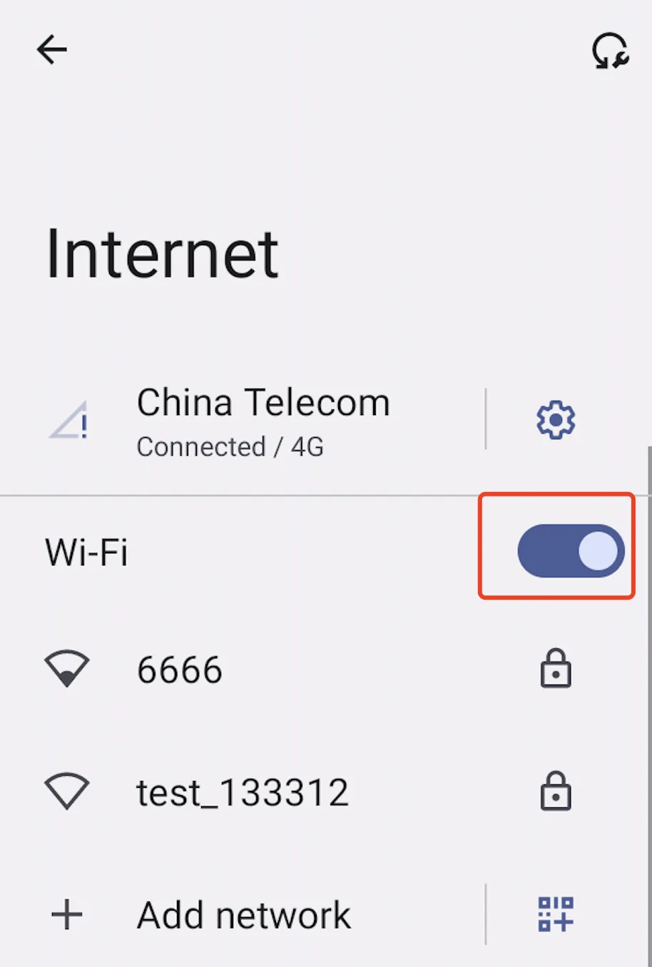
Figure 3-5 Wi-Fi Settings (Android 12)
- In the Wi-Fi networks list, select the target Wi-Fi network.
- When an encrypted network is selected, the password entry dialog box pops up automatically. Enter the password and click "CONNECT".
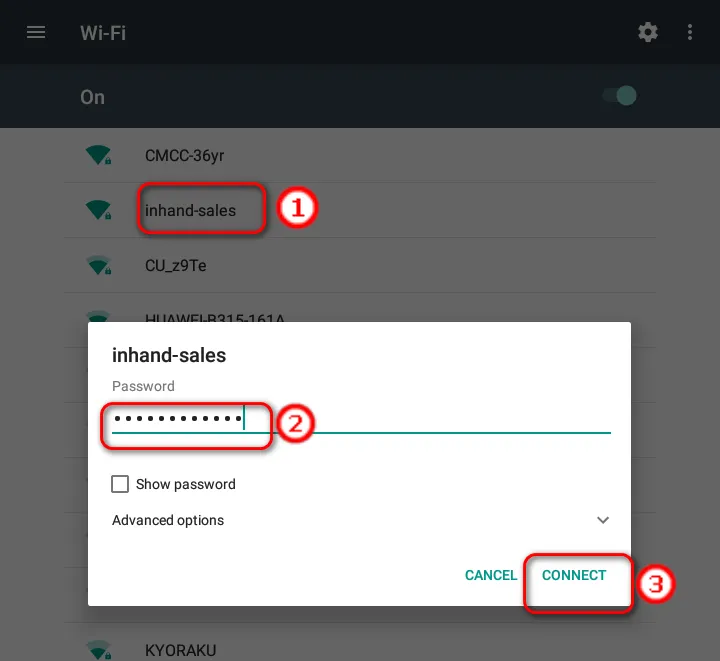
Figure 3-6 Wi-Fi Password Entry
Verification Method: 1. The connected Wi-Fi network is displayed in the network list. 2. Click the connected network to display status information, signal strength, connection speed, security, and frequency.
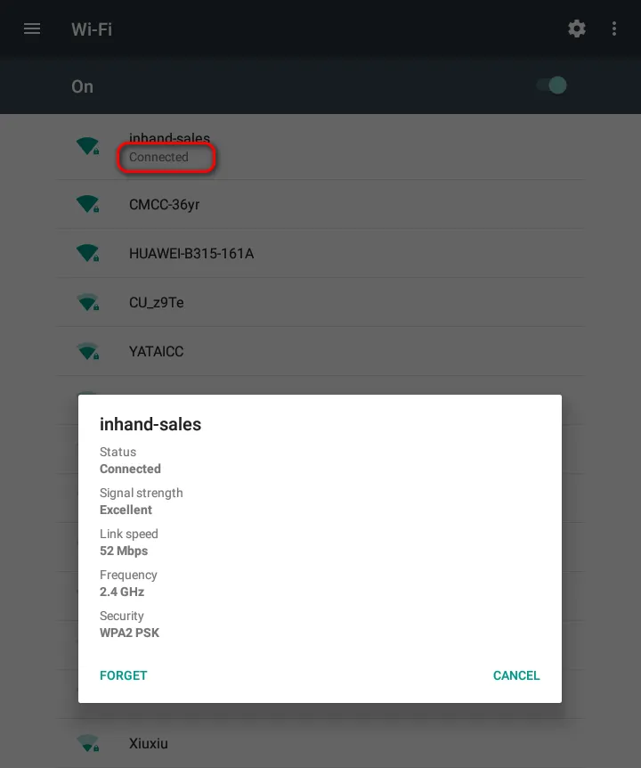
Figure 3-7 Wi-Fi Connection Status
Common Issues: - Connection failure: Verify the Wi-Fi password is correct. - Weak signal: Move the device closer to the access point or check the antenna connection. - To remove a saved network: Select "FORGET" in the current network information dialog box.
Scenario 3: Ethernet Configuration
Objective: Configure the Ethernet port as WAN or LAN interface.
Prerequisites: Ethernet cable is available. Device is powered on.
Estimated Time: ~5 minutes.
Operation Steps: 1. Connect the Ethernet cable to the network port on the device. 2. If the current system is Android 7.1: Navigate to Settings → Ethernet. If the current system is Android 12: Navigate to Settings → Network \& internet → Ethernet. 3. Click "Use Ethernet" to enable the Ethernet port.
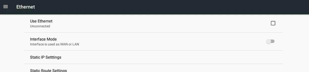
Figure 3-8 Ethernet Settings
- By default, Ethernet is used as WAN interface and obtains IP address through DHCP.
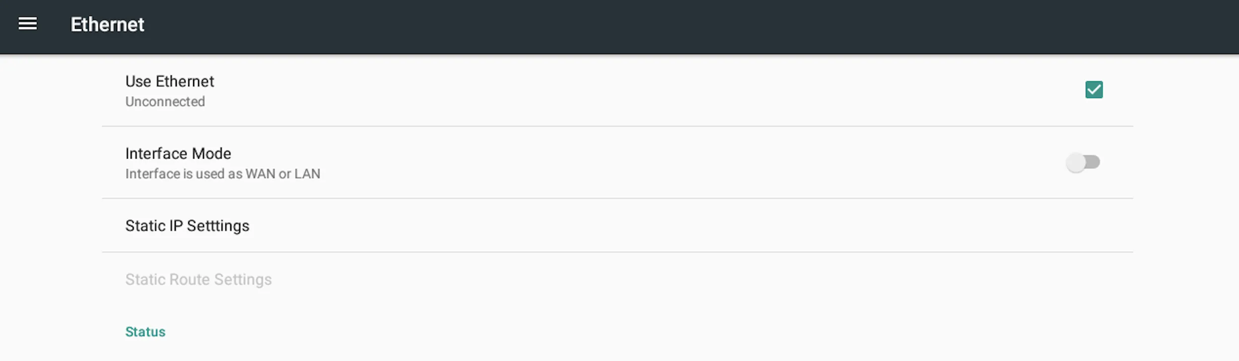
Figure 3-9 WAN Interface
- To set a static IP address for WAN: Click "Static IP Settings", enable "Use static IP", and configure the IP address, netmask, default gateway, preferred DNS server, and alternative DNS server. Click "SAVE".
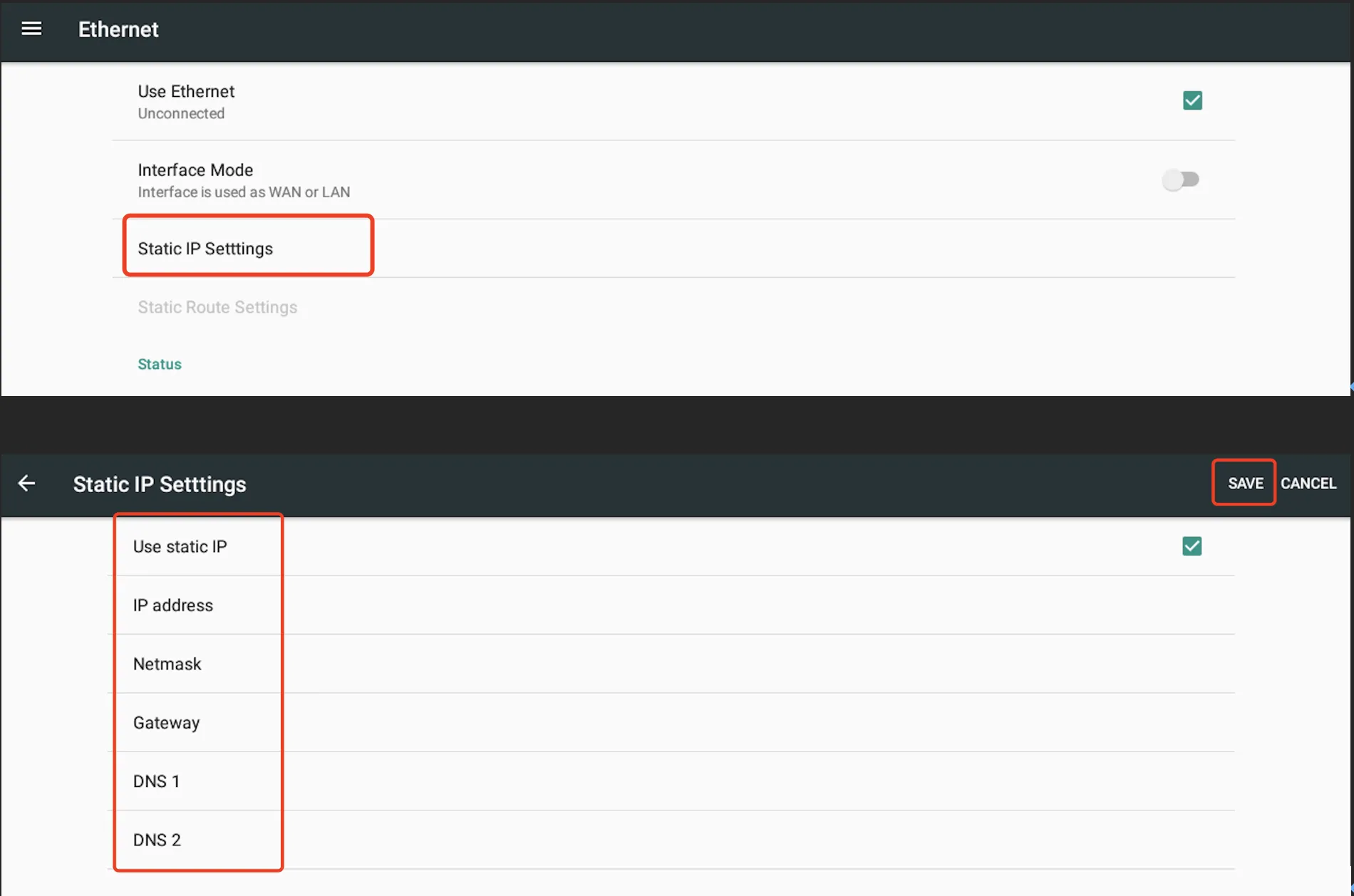
Figure 3-10 Static IP Settings
- To use Ethernet as LAN interface: On the Ethernet page, click "Interface mode" and select LAN. The default LAN IP address is 192.168.1.100 and the mask is 255.255.255.0.
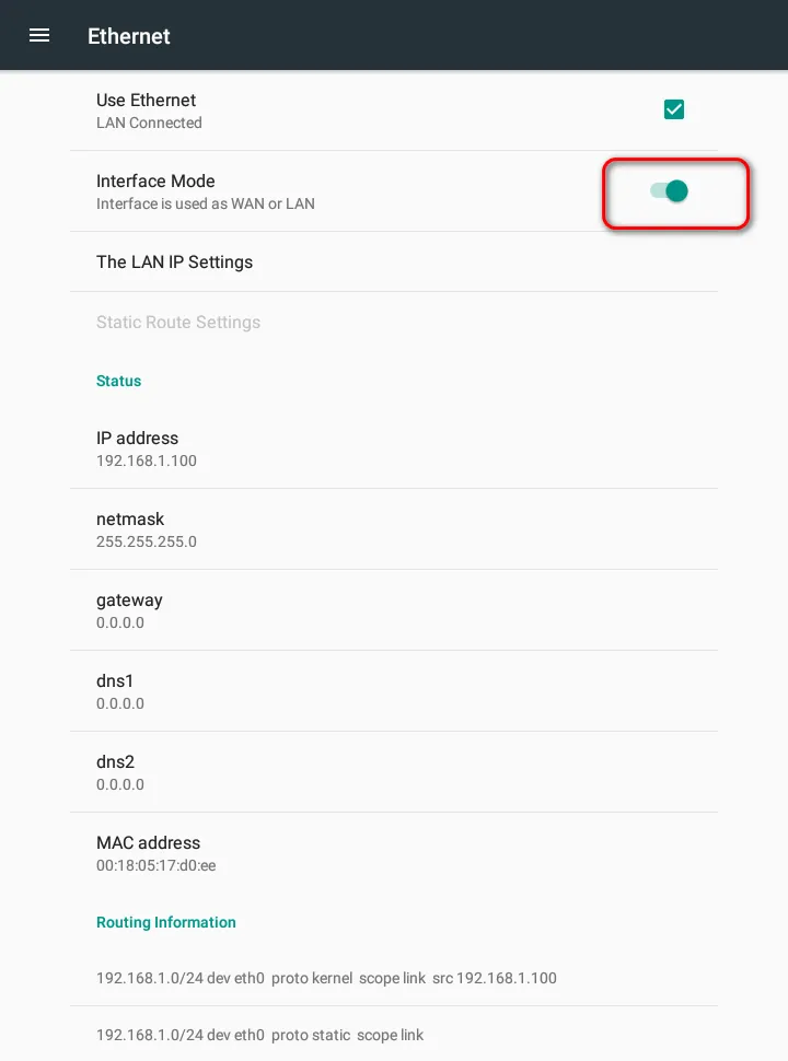
Figure 3-11 LAN Interface
- To customize LAN IP settings: Click "LAN IP Settings", modify the IP address and netmask, and click "SAVE".
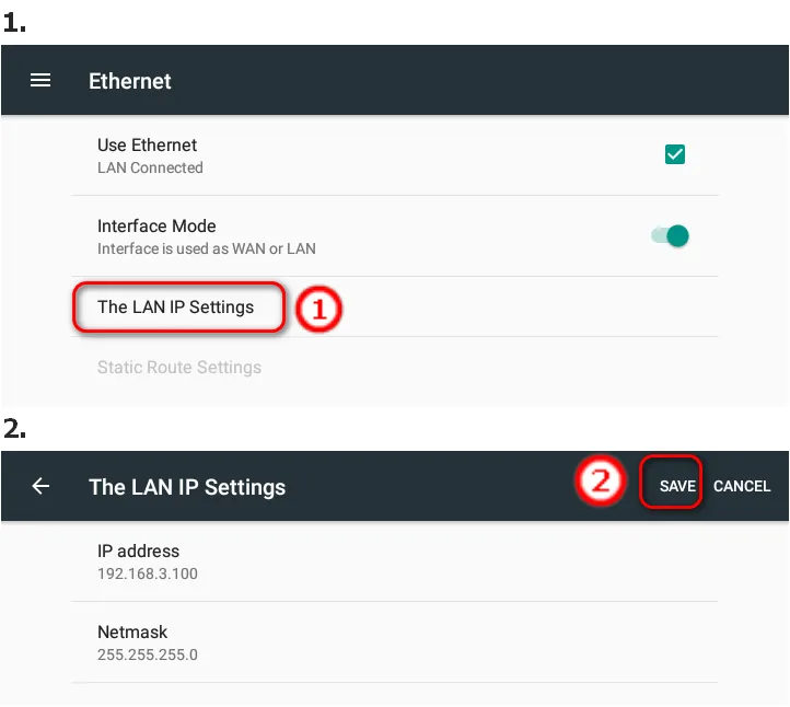
Figure 3-12 LAN IP Settings
Verification Method: 1. On the Ethernet page, verify the IP address, netmask, default gateway, and DNS server information are displayed correctly. 2. Open a web browser and access an internet website to confirm connectivity.
Common Issues: - No IP address obtained: Verify the Ethernet cable is connected and the upstream DHCP server is functioning. - Cannot access the internet: Verify the gateway and DNS settings are correct.
Scenario 4: Display Settings
Objective: Configure display mode and screen rotation.
Prerequisites: Device is powered on and the display is functioning.
Estimated Time: ~5 minutes.
Full Screen Mode
Operation Steps: 1. Navigate to Settings → Display. 2. Enable "Full Screen" display.
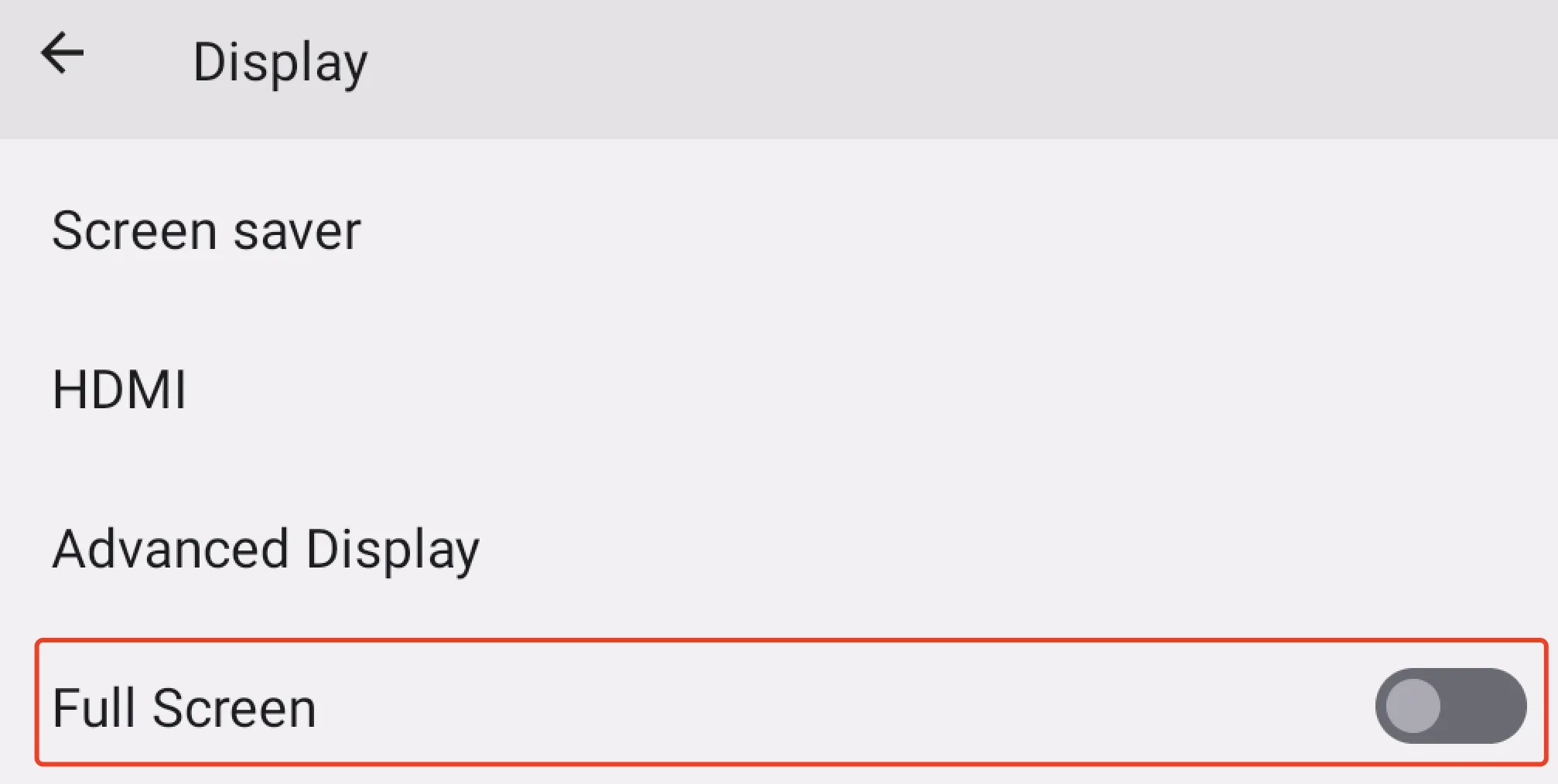
Figure 3-13 Full Screen Setting
- After the prompt box "The device needs to be restarted for the settings to take effect" appears, click "OK".
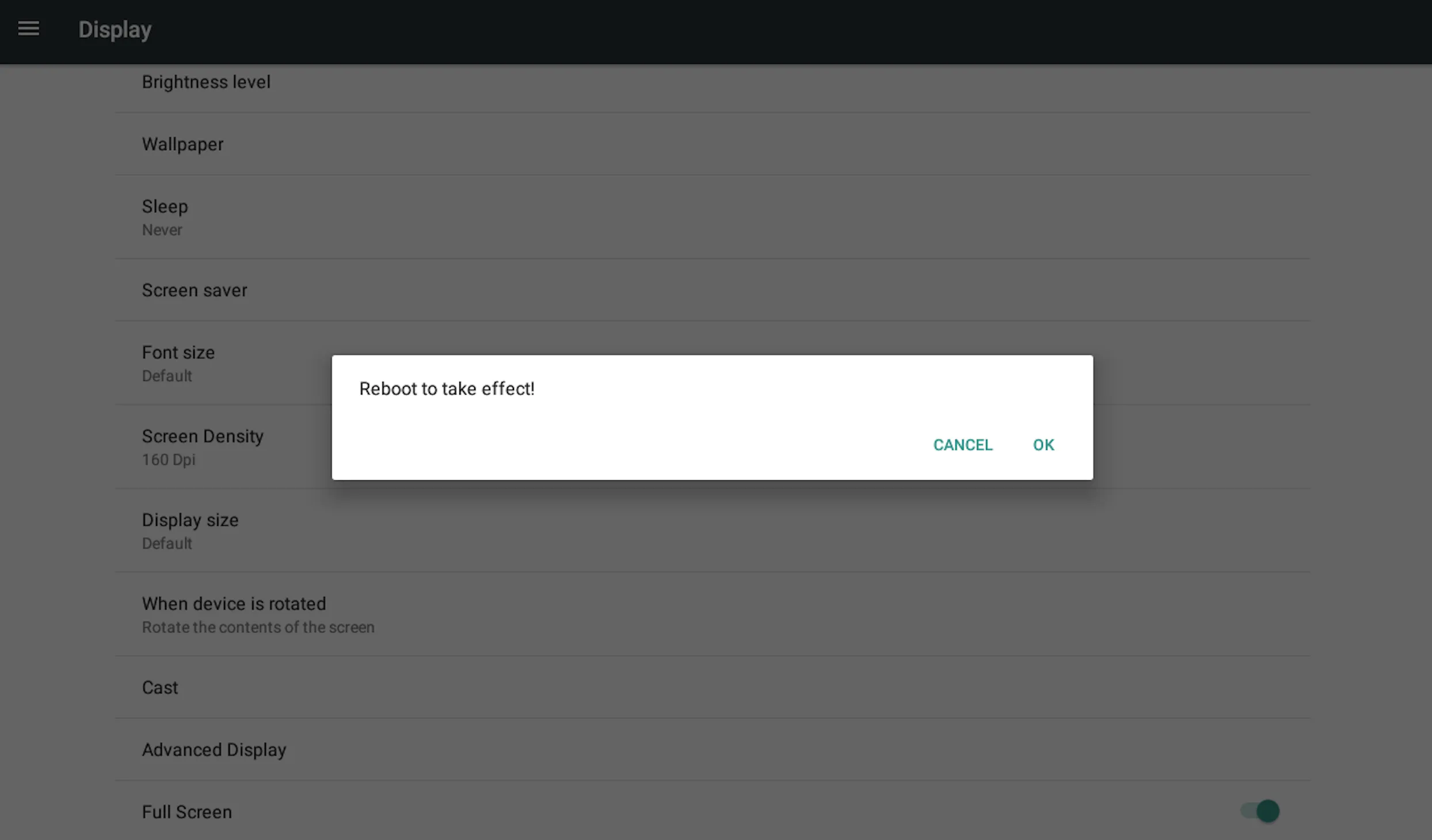
Figure 3-14 Restart Prompt
- The device will restart and display in full screen mode.
Screen Rotation
Operation Steps: 1. Navigate to Settings → Display → Advanced Display. 2. Select "Rotation" to open the rotation setting dialog box. 3. Select the required rotation direction.
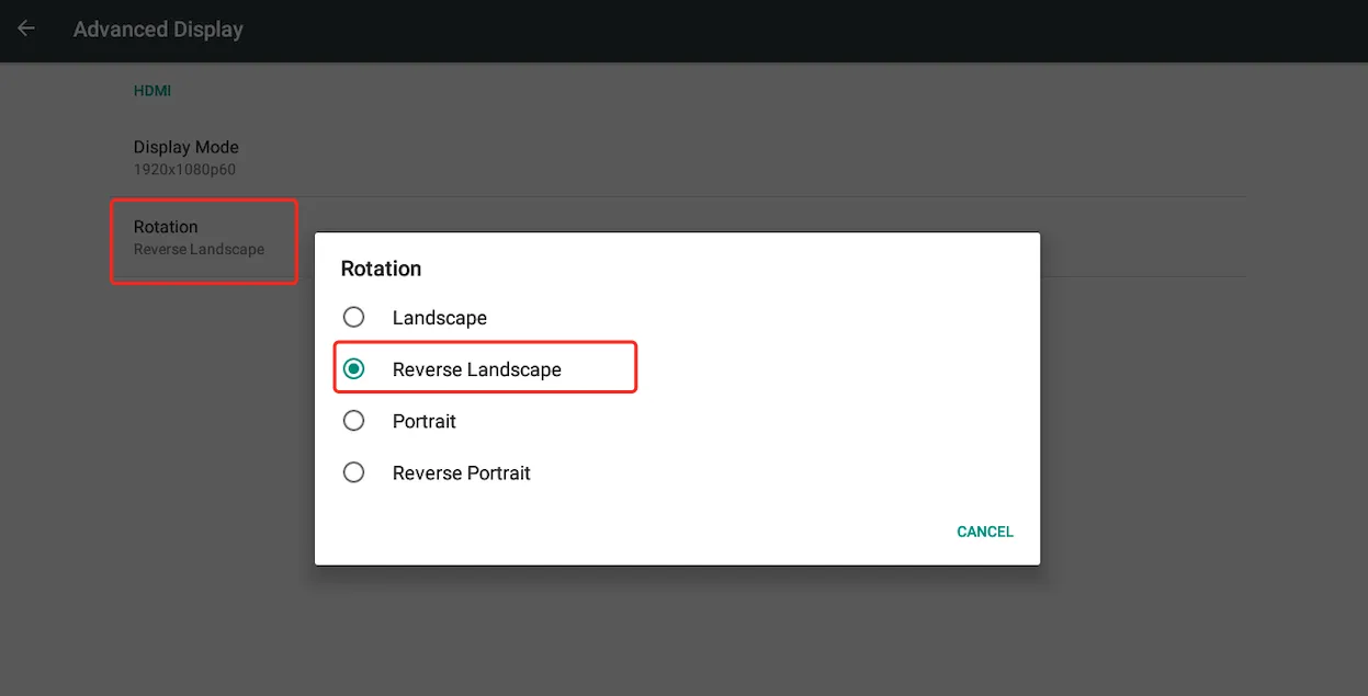
Figure 3-15 Rotation Setting
- After selecting the rotation, click "OK" in the pop-up dialog box of "Configuration Change, Need reboot".
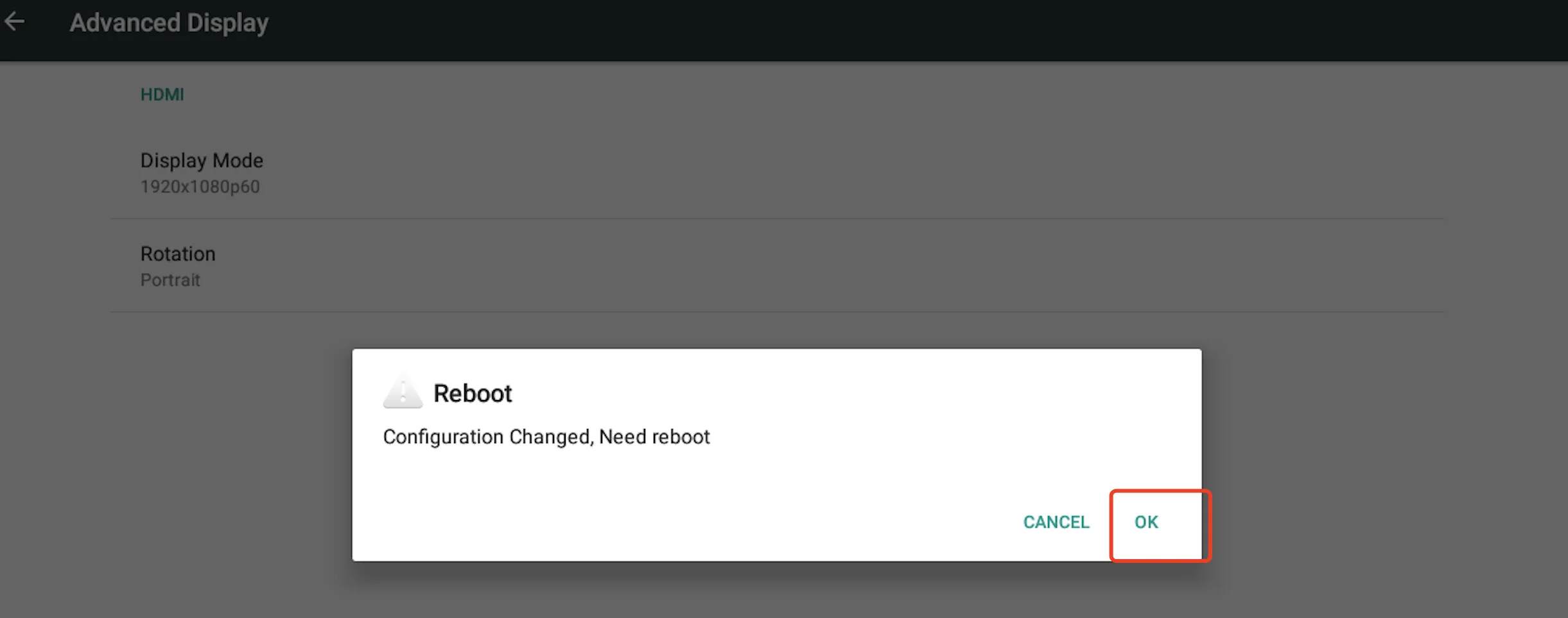
Figure 3-16 Reboot Prompt
- The device will reboot to apply the configuration.
Verification Method: 1. After reboot, verify the display is in the selected mode (full screen or rotated).
Common Issues: - Rotation not applied: Verify the device was rebooted after configuration change.
Scenario 5: System Upgrade
Objective: Upgrade the device firmware to a newer version.
Prerequisites: Upgrade file (update.zip) is prepared. USB storage device is available (for Method 1). ADB access is available (for Method 2).
Estimated Time: ~10 minutes.
Method 1: Upgrade with USB Storage in Android System
Operation Steps: 1. Rename the upgrade file as "update.zip" and copy it to a USB storage device. 2. Plug the USB storage device into the InPAD device. 3. If the current system is Android 7.1: Navigate to Settings → About tablet → Udisk system updates. If the current system is Android 12: Navigate to Settings → System → Udisk system updates. 4. The system will automatically upgrade and restart.
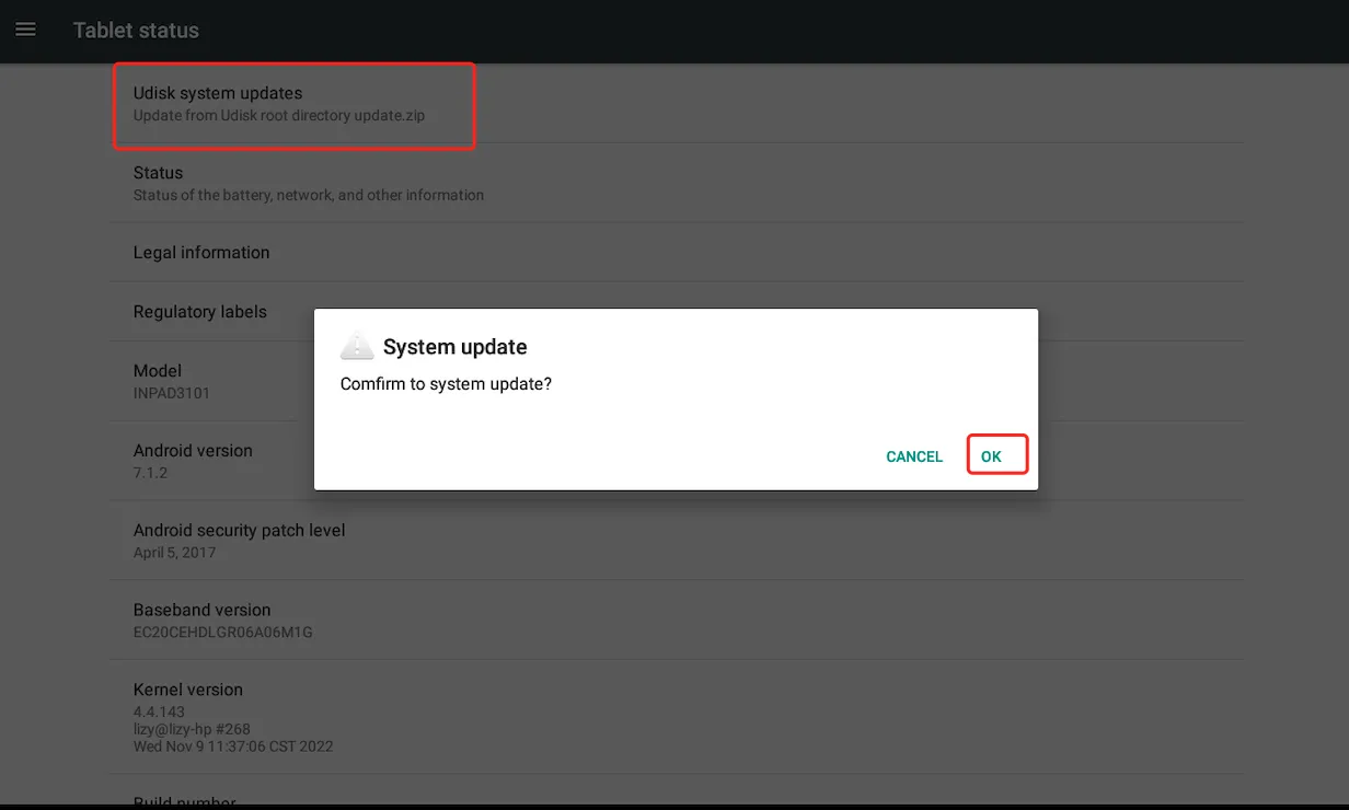
Figure 3-17 USB System Upgrade
Method 2: Upgrade via ADB Broadcast Command
Operation Steps: 1. Rename the upgrade file to "update.zip" and copy it to the /sdcard directory of the device. 2. Enable USB debugging in the Developer options. 3. Execute the ADB command:
Note: Method 2 can be used for FOTA (Firmware Over-The-Air) of InPAD devices. Download the upgrade file to the "/sdcard" directory, rename it to update.zip, and execute the broadcast command:
am broadcast -a com.ubox.upgraderom --include-stopped-packages.
Verification Method: 1. After reboot, navigate to Settings → About tablet and verify the system version number.
Common Issues: - Upgrade fails: Verify the upgrade file is correctly named "update.zip" and is not corrupted. - ADB command fails: Verify USB debugging is enabled and the device is properly connected.
Scenario 6: Application Installation
Objective: Install third-party applications on the device.
Prerequisites: The APK installation file is available on the device or external storage.
Estimated Time: ~5 minutes.
Operation Steps: 1. Select the "File Explorer" application. 2. Find the installation file (APK file) in the "File" tab and click it. 3. The installation prohibition dialog box will pop up for the first installation. Click "SETTINGS". 4. Enable "Unknown source" in the "Security" interface.
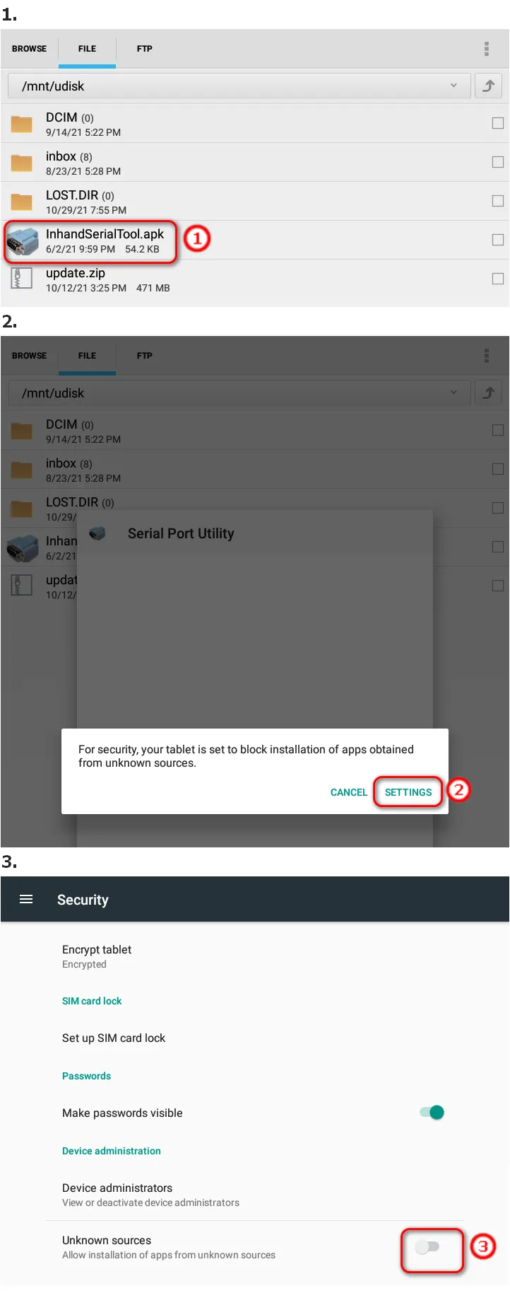
Figure 3-18 Unknown Source Setting
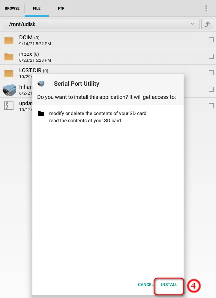
Figure 3-19 Security Settings
- Return to the File Explorer and click the installation file again to complete installation.
Verification Method: 1. Verify the application icon appears on the desktop or in the application list. 2. Launch the application to confirm it runs correctly.
Common Issues: - Installation blocked: Verify "Unknown source" is enabled in Security settings. - Parse error: Verify the APK file is compatible with the Android version and not corrupted.
Chapter 4: Function Description and Parameter Reference
4.1 Developer Options
4.1.1 Function Description
Developer options provide advanced system functions for developers and technical personnel, including system logging, USB debugging, and hardware watchdog.
4.1.2 Access Path
If the current system is Android 7.1: Settings → About Tablet → Build number (click 5 times continuously). If the current system is Android 12: Settings → About tablet → Android security patch level (click 2 times) → Baseband version (click 3 times) → Android security patch level (click 4 times) → Build number (click until "You are now a developer" appears).
After entering developer mode, "Developer options" will appear in Settings or System (Android 12).
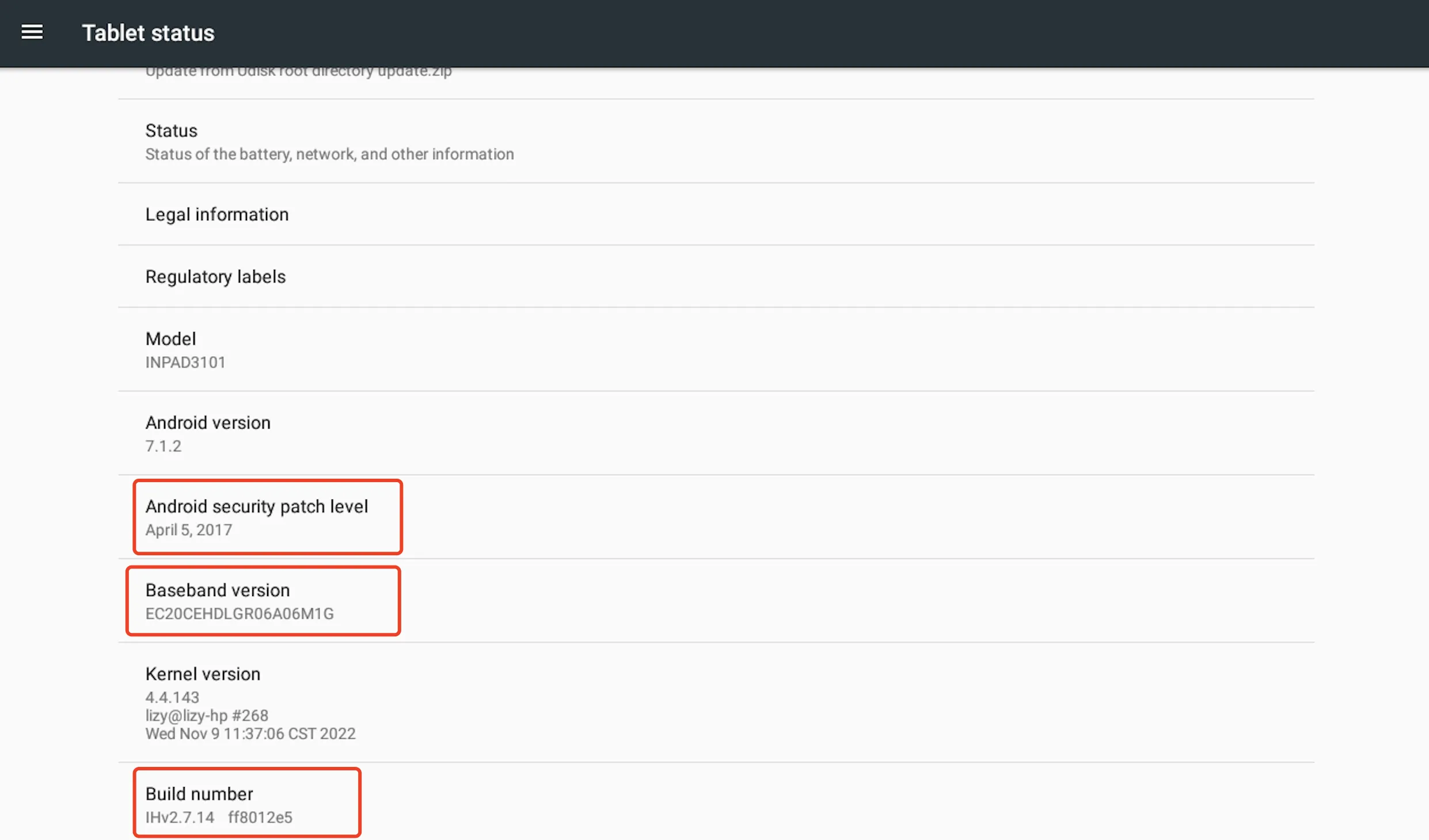
Figure 4-1 Developer Options
4.1.3 Operation Description
Commonly used function items in developer options include:
- Logging: After enabled, the system records logs to the /data/logger directory.
- USB debugging: After enabled, users can access the device through the ADB interface.
- Hardware watchdog: Once enabled, a restart is required to take effect.
4.1.4 Parameter Description
| Parameter | Description | Default Value |
|---|---|---|
| Logging | System log recording | Disabled |
| USB debugging | ADB interface access | Disabled |
| Hardware watchdog | Automatic system recovery | Disabled |
4.2 System Upgrade
4.2.1 Function Description
The system upgrade function allows users to update the device firmware to a newer version. Three upgrade methods are supported: USB storage upgrade in Android system, recovery mode upgrade, and ADB broadcast command upgrade.
4.2.2 Access Path
- USB upgrade (Android 7.1): Settings → About tablet → Udisk system updates
- USB upgrade (Android 12): Settings → System → Udisk system updates
- ADB upgrade: Via ADB shell command
4.2.3 Operation Description
Refer to Scenario 5: System Upgrade for detailed operation steps.
4.2.4 Parameter Description
| Parameter | Description |
|---|---|
| Upgrade file name | Must be renamed to "update.zip" |
| Upgrade file location | USB storage root directory or /sdcard |
| ADB command | adb shell am broadcast -a com.ubox.upgraderom --include-stopped-packages |
4.3 Display Settings
4.3.1 Function Description
Display settings allow users to configure the screen display mode (full screen) and rotation direction.
4.3.2 Access Path
- Full screen: Settings → Display
- Rotation: Settings → Display → Advanced Display → Rotation
4.3.3 Operation Description
Full Screen: 1. Navigate to Settings → Display. 2. Enable "Full Screen" display. 3. Click "OK" in the restart prompt dialog. 4. The device will restart and apply full screen mode.
Screen Rotation: 1. Navigate to Settings → Display → Advanced Display. 2. Select "Rotation" to open the rotation setting dialog. 3. Select the required rotation direction. 4. Click "OK" in the reboot prompt dialog. 5. The device will reboot to apply the rotation.
4.3.4 Parameter Description
| Parameter | Options | Description |
|---|---|---|
| Full Screen | Enable / Disable | Enable or disable full screen display |
| Rotation | 0° / 90° / 180° / 270° | Screen rotation direction |
4.4 Ethernet Settings
4.4.1 Function Description
The Ethernet port of InPAD can be used as WAN port or LAN port. It is disabled by default.
4.4.2 Access Path
- Android 7.1: Settings → Ethernet
- Android 12: Settings → Network \& internet → Ethernet
4.4.3 Operation Description
Enable Ethernet: 1. Navigate to the Ethernet settings page. 2. Click "Use Ethernet" to enable the Ethernet port.
Configure as WAN: 1. Enable Ethernet. The port is used as WAN by default. 2. The WAN interface obtains IP address through DHCP by default. 3. To set static IP: Click "Static IP Settings", enable "Use static IP", and configure IP address, netmask, gateway, and DNS.
Configure as LAN: 1. On the Ethernet page, click "Interface mode" and select LAN. 2. The default LAN IP is 192.168.1.100 with mask 255.255.255.0. 3. To customize: Click "LAN IP Settings" and modify the IP address and netmask.
4.4.4 Parameter Description
| Parameter | Default Value | Description |
|---|---|---|
| Ethernet mode | Disabled | WAN or LAN |
| WAN IP mode | DHCP | DHCP or Static IP |
| Static IP address | - | User-defined |
| Static netmask | - | User-defined |
| Static gateway | - | User-defined |
| Static DNS | - | User-defined |
| LAN IP address | 192.168.1.100 | LAN interface IP |
| LAN netmask | 255.255.255.0 | LAN subnet mask |
4.5 Wi-Fi Settings
4.5.1 Function Description
Wi-Fi settings allow the device to scan and connect to surrounding wireless networks. The device supports WPA/WPA2 protected networks.
4.5.2 Access Path
- Android 7.1: Settings → Wi-Fi
- Android 12: Settings → Network \& internet → Internet → Wi-Fi
4.5.3 Operation Description
- Ensure the Wi-Fi antenna is connected.
- Navigate to Wi-Fi settings and turn on the Wi-Fi switch.
- Select a network from the scanned list.
- Enter the password for encrypted networks and click "CONNECT".
- To view connection details: Click the connected network to display status, signal strength, connection speed, security, and frequency.
- To remove a network: Select "FORGET" in the network information dialog.
- To view MAC and IP address: Click the settings symbol in the upper right corner.
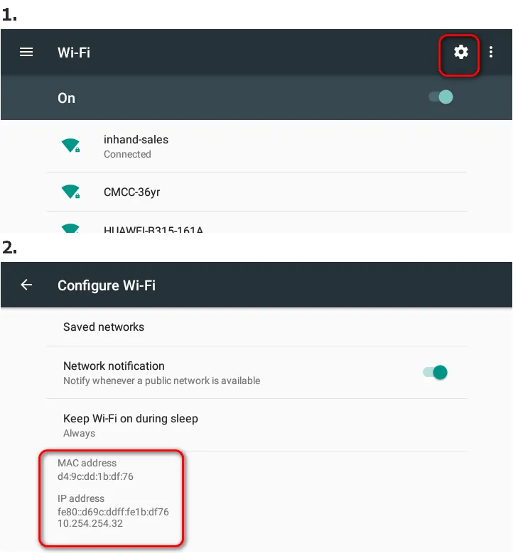
Figure 4-3 Wi-Fi MAC and IP Address
4.5.4 Parameter Description
| Parameter | Description |
|---|---|
| SSID | Wi-Fi network name |
| Security | Open network or WPA/WPA2 protection |
| Signal strength | Current connection signal level |
| Connection speed | Link rate |
| Frequency | Operating frequency band |
| MAC address | Wi-Fi interface MAC address |
| IP address | Assigned IP address |
4.6 4G Settings
4.6.1 Function Description
4G settings allow the device to connect to cellular networks for internet access. APN (Access Point Name) configuration is required for proper network registration.
4.6.2 Access Path
- Android 7.1: Settings → More → Cellular networks → Access Point Names
- Android 12: Settings → Network \& internet → SIMs → Access Point Names
4.6.3 Operation Description
APN Configuration: 1. Navigate to the Access Point Names page. 2. Click the add symbol in the upper right corner. 3. Fill in the Name and APN (obtained from the carrier). 4. Click the save symbol in the upper right corner. 5. In the APN list, select the newly added APN.
ICMP Detection: 1. Navigate to the ICMP detection page (Android 7.1: Settings → More → ICMP detection; Android 12: Settings → Network \& internet → ICMP detection). 2. ICMP detection is enabled by default. 3. Click "Configure ICMP detail" to set detection server parameters. 4. Click "Save" to save the configuration.
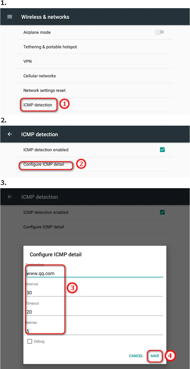
Figure 4-4 ICMP Detection
4.6.4 Parameter Description
| Parameter | Description | Default Value |
|---|---|---|
| APN Name | Access point name | User-defined |
| APN | Carrier network identifier | User-defined |
| ICMP detection | Network connectivity detection | Enabled |
| Detection server | ICMP target server address | User-defined |
4.7 File Management
4.7.1 Function Description
File management allows users to browse files and folders on the system and external storage devices.
4.7.2 Access Path
File Explorer application
4.7.3 Operation Description
- Select the "File Explorer" application.
- Browse files and folders in the system.
- External storage devices can also be accessed.
4.7.4 Parameter Description
| Parameter | Description |
|---|---|
| Built-in SD card path | /mnt/sdcard |
4.8 Application Management
4.8.1 Function Description
Application management allows users to install third-party APK files and uninstall existing applications.
4.8.2 Access Path
- Installation: File Explorer → select APK file
- Uninstallation: Settings → Apps → select application → UNINSTALL
4.8.3 Operation Description
Installation: 1. Select the "File Explorer" application. 2. Find the APK file in the "File" tab and click it. 3. For first installation, enable "Unknown source" in Security settings when prompted. 4. Click the installation file again to complete installation.
Uninstallation: 1. Navigate to Settings → Apps. 2. Click the application to be uninstalled. 3. Click "UNINSTALL" and confirm.
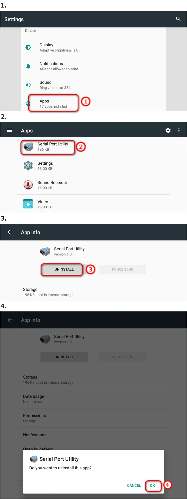
Figure 4-4 Application Uninstallation
4.9 Serial Port Test
4.9.1 Function Description
Serial port test verifies whether the serial port communication on InPAD is working normally.
4.9.2 Access Path
Serial port test APP (third-party application)
4.9.3 Operation Description
- Connect the serial port on the InPAD to the serial port on the PC with a serial converter.
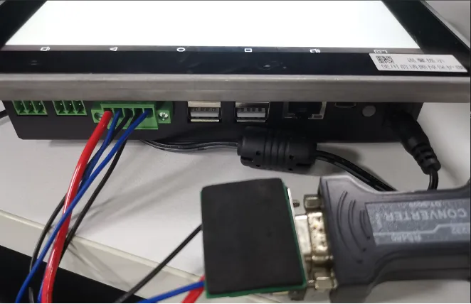
Figure 4-5 Serial Port Connection
- View the connected serial port through the device manager on the PC.
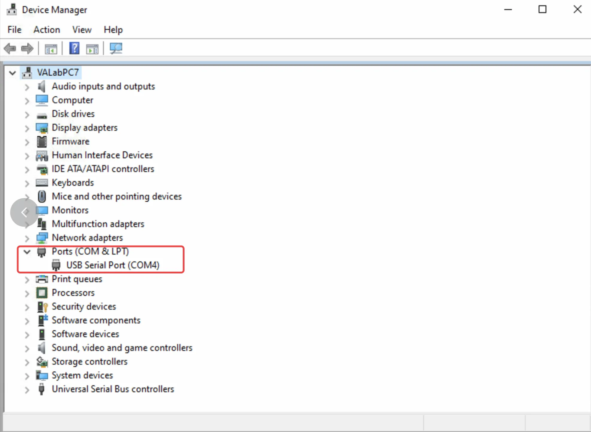
Figure 4-6 Device Manager Serial Port
- Download and run the serial port test APP on the device.
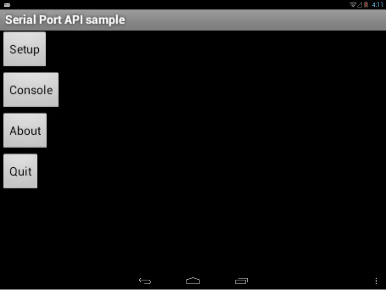
Figure 4-7 Serial Port Test APP
- Click setup, select the connected serial port in Device, and set the baud rate.
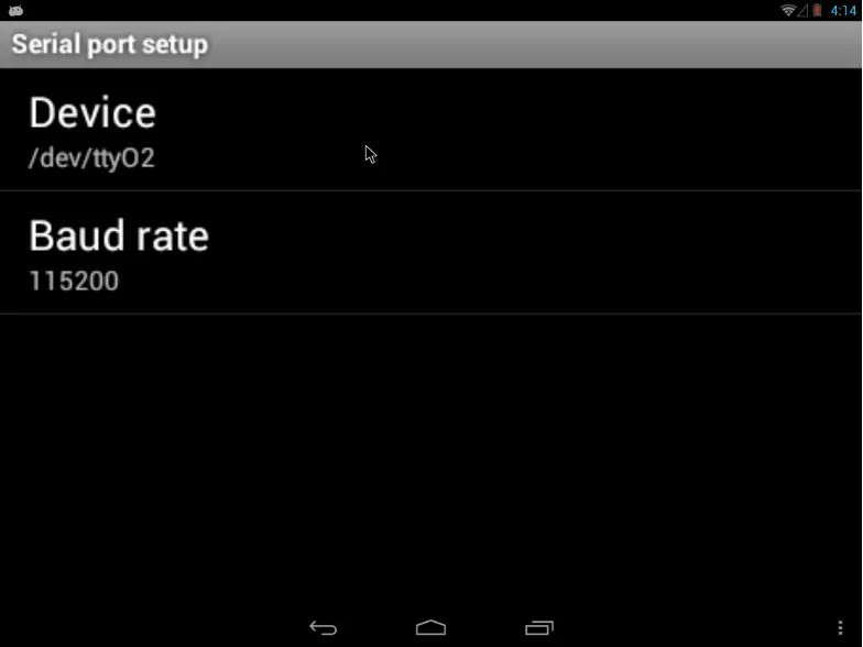
Figure 4-8 Serial Port Setup
- Open "Console" after configuration.
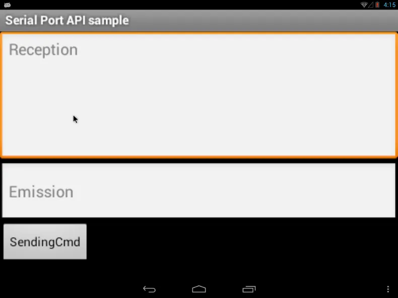
Figure 4-9 Serial Console
- Open the serial port assistant on the PC side, set the correct port, and configure the baud rate to be consistent.
- Test the serial port by sending data from both the device and PC sides.
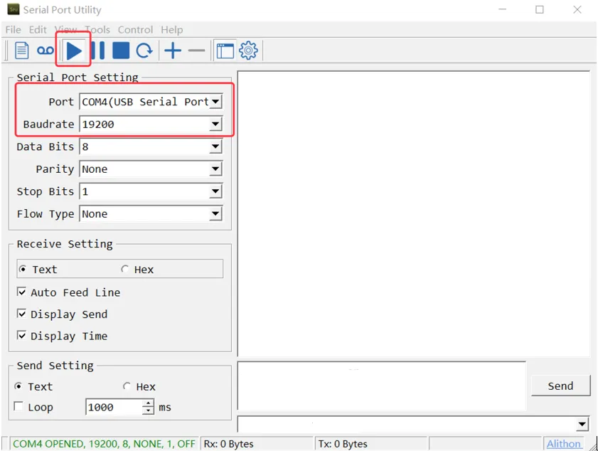
Figure 4-10 PC Serial Port Assistant
4.9.4 Parameter Description
| Parameter | Description |
|---|---|
| Serial port | ttyS2, ttyS4 (RS485); RS232 serial ports |
| Baud rate | Configurable (must match on both sides) |
| Data bits | Configurable |
| Stop bits | Configurable |
| Parity | Configurable |
4.10 Backup and Reset
4.10.1 Function Description
Factory data reset restores the device to its original factory state, clearing all user data and settings.
4.10.2 Access Path
- Android 7.1: Settings → Backup \& reset → Factory data reset → RESET TABLET
- Android 12: Settings → System → Reset options → Erase all data → RESET TABLET
4.10.3 Operation Description
- Navigate to the factory reset page.
- Click "RESET TABLET".
- Confirm the reset operation.
Warning: Use this function with caution. After factory reset, all data on the product will be cleared.
4.10.4 Parameter Description
| Parameter | Description |
|---|---|
| Factory data reset | Restores device to factory default state |
4.11 Power Button
4.11.1 Function Description
The power button controls device power state and restart operations.
4.11.2 Operation Description
Press and hold the power button for more than 1 second, then select restart to reboot the device.
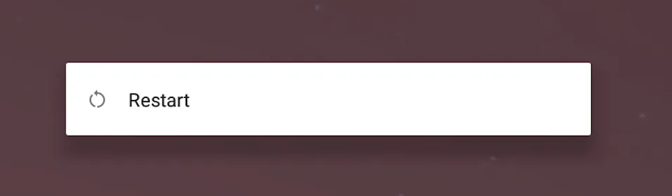
Figure 4-11 Power Button Menu
4.11.3Parameter Description
| Parameter | Description |
|---|---|
| Long press duration | > 1 second |
| Function | Power menu / Restart |
4.12 MODE Button
4.12.1 Function Description
The MODE button can be programmed to realize special functions.
Chapter 5: Typical Applications
Case 1: Industrial HMI and Data Collection Terminal
Scenario Description: InPAD series devices are deployed in industrial environments as human-machine interface (HMI) terminals and data collection gateways. The device connects to PLCs and sensors through RS485/RS232 serial ports, collects real-time production data, and uploads it to a cloud management platform via 4G cellular or Wi-Fi network.
Network Topology:
Figure 5-1 Industrial HMI Network Topology
Device Role: The InPAD device serves as an edge gateway and HMI terminal, responsible for serial data collection, local display, protocol conversion, and cloud data upload.
Configuration Steps: 1. Install the device at the industrial site using VESA or M3 hole mounting. 2. Connect the grounding cable to improve anti-interference capability. 3. Connect RS485/RS232 cables from PLCs/sensors to the device serial ports. 4. Insert a SIM card and install the 4G antenna for cellular network access. 5. Configure APN parameters according to Scenario 1: Cellular Network Access. 6. Alternatively, connect to the site Wi-Fi according to Scenario 2: Wi-Fi Connection. 7. Install the data collection application via Scenario 6: Application Installation. 8. Configure the serial port parameters (baud rate, data bits, etc.) in the application. 9. Verify data collection and cloud upload functionality.
Reference Chapters: - Serial Port Test - 4G Settings - Wi-Fi Settings - Application Installation
Case 2: Remote Monitoring Terminal
Scenario Description: InPAD devices are deployed in remote or distributed locations (such as vending machines, charging stations, or environmental monitoring sites) as monitoring terminals. The device displays operational status on the touch screen and transmits monitoring data to a central management platform through 4G network.
Network Topology:
Figure 5-2 Remote Monitoring Network Topology
Device Role: The InPAD device serves as a remote monitoring terminal and edge gateway, responsible for local status display, data buffering, and remote data transmission.
Configuration Steps: 1. Mount the device at the monitoring site. 2. Connect power and grounding. 3. Install the cellular antenna and insert a SIM card. 4. Configure the APN for cellular network access according to Scenario 1: Cellular Network Access. 5. Configure display settings (full screen or rotation) as needed according to Scenario 4: Display Settings. 6. Install the monitoring application. 7. Configure the monitoring parameters and server address in the application. 8. Verify data transmission to the central platform.
Reference Chapters: - Display Settings - Cellular Network Access - Application Installation
Appendix A: Troubleshooting
A.1 Network Connection Issues
| Symptom | Possible Cause | Troubleshooting Steps | Reference Chapter |
|---|---|---|---|
| Cannot connect to cellular network | SIM card not inserted or poor contact | 1. Check if SIM card is correctly inserted 2. Re-insert the SIM card |
SIM Card Installation |
| Cannot connect to cellular network | APN parameter configuration error | 1. Verify APN parameters are correct 2. Contact carrier for correct APN |
Cellular Network Configuration |
| Cannot connect to cellular network | Weak signal or no signal | 1. Check if antenna is connected 2. Adjust device position |
Cellular Network Configuration |
| Wi-Fi connection fails | Incorrect password | 1. Re-enter the Wi-Fi password 2. Verify password with network administrator |
Wi-Fi Connection |
| Wi-Fi connection fails | Weak signal | 1. Move device closer to access point 2. Check Wi-Fi antenna connection |
Wi-Fi Connection |
| Cannot obtain IP via Ethernet | Cable not connected | 1. Check Ethernet cable connection 2. Replace cable if damaged |
Ethernet Configuration |
| Cannot obtain IP via Ethernet | DHCP server unavailable | 1. Verify upstream network device is functioning 2. Configure static IP instead |
Ethernet Configuration |
A.2 Display Issues
| Symptom | Possible Cause | Troubleshooting Steps | Reference Chapter |
|---|---|---|---|
| Screen not displaying | Power not connected | 1. Check power cable connection 2. Verify power adapter output is 12V DC |
Power Connection |
| Screen not displaying | Device not powered on | 1. Check power indicator status 2. Long press power button to start |
Power Button |
| Touch not responding | Screen frozen | 1. Restart the device 2. Check for application conflicts |
Power Button |
| Display rotation not applied | Device not rebooted | 1. Reboot device after changing rotation settings | Display Settings |
A.3 System Issues
| Symptom | Possible Cause | Troubleshooting Steps | Reference Chapter |
|---|---|---|---|
| System runs slowly | Too many applications running | 1. Close unused applications 2. Uninstall unnecessary applications |
Application Management |
| Application crashes | Incompatible application | 1. Uninstall the problematic application 2. Install a compatible version |
Application Management |
| Cannot install application | Unknown sources disabled | 1. Enable "Unknown source" in Security settings | Application Installation |
| System upgrade fails | Corrupted upgrade file | 1. Re-download the upgrade file 2. Verify file is named "update.zip" |
System Upgrade |
A.4 Serial Communication Issues
| Symptom | Possible Cause | Troubleshooting Steps | Reference Chapter |
|---|---|---|---|
| Serial port no data | Incorrect baud rate | 1. Verify baud rate matches on both sides | Serial Port Test |
| Serial port no data | Wrong serial port selected | 1. Verify correct port in device manager 2. Check physical connection |
Serial Port Test |
| Garbled data | Mismatched data format | 1. Verify data bits, stop bits, and parity settings | Serial Port Test |
Appendix B: Safety Precautions
- The device shall be used within the specified temperature and humidity ranges (operating temperature: -10°C to 60°C; relative humidity: 5% to 95%, non-condensing).
- Do not use the device in flammable or explosive environments.
- Before connecting power, verify the voltage meets the device specification (12 V DC).
- Keep the device out of direct sunlight and away from heat sources.
- Keep the device away from areas with strong electromagnetic interference.
- Do not disassemble or modify the device. Doing so will void the warranty.
- Ensure proper grounding to improve anti-interference capability.
- Use only approved accessories and power adapters.
Warning: Non-professionals should not open the device enclosure. Risk of electric shock.
Caution: Improper operation may cause data loss or damage to the device.
FAQ
Q1: What is the difference between InPAD070S and InPAD3101?
The main difference is the display size and resolution. InPAD070S features a 7-inch display with resolution of 1024 x 600. InPAD3101 features a 10.1-inch display with resolution of 1280 x 800. All other interfaces and functions are identical.
Q2: How to distinguish between Android 7.1 and Android 12 system settings paths?
Android 7.1 system settings are organized in a flat structure (e.g., Settings → Ethernet). Android 12 system settings are reorganized under Network \& internet and System categories (e.g., Settings → Network \& internet → Ethernet). Refer to the specific operation steps in each chapter for the correct path.
Q3: 4G cannot connect to the internet?
- Physical environment: Check whether the SIM card is inserted into the correct slot and whether the cellular antenna is installed.
- APN settings: Ensure the APN configuration matches the information provided by the carrier.
- Check device connectivity: Log in to the device and use the ICMP tool to ping 8.8.8.8 to test connectivity.
- Verify SIM card: Remove the SIM card and install it in a mobile phone to check whether it can access the internet normally.
- Restart: Power off the device, wait a few seconds, and reconnect power to retry.
- Factory reset: Restore the device to factory settings and retry.
Q4: How to enable full screen mode?
Navigate to Settings → Display, enable "Full Screen", and click "OK" in the restart prompt. The device will reboot and display in full screen mode.
Q5: How to perform a factory reset?
For Android 7.1: Navigate to Settings → Backup \& reset → Factory data reset → RESET TABLET. For Android 12: Navigate to Settings → System → Reset options → Erase all data → RESET TABLET. Note: All data will be cleared after factory reset. Use with caution.
Q6: How to connect the device to a PC for debugging?
- Enable USB debugging in Developer options.
- Connect the device to the PC using a Micro USB cable.
- Use ADB commands to access the device.
Q7: What file path is used for the built-in SD card?
The built-in SD card path is /mnt/sdcard.