InHand VG814 User Manual (Standard Edition) V1.2
Front Matter
Copyright and Conventions
This user manual contains copyrighted content, and the copyright belongs to InHand Networks and its licensors. Without written permission, no organization or individual may excerpt, copy any part of the content of this manual, or distribute it in any form.
Due to ongoing updates in product technology and specifications, the company cannot guarantee that the information in the user manual is entirely consistent with the actual product. Therefore, no disputes arising from any discrepancies between the actual technical parameters and the user manual are accepted. Any changes to the product will not be notified in advance, and the company reserves the right to make the final changes and interpretations.
Conventions
| Symbol | Indication |
|---|---|
| > | Indicates a button name, for example, the OK button |
| "" | Indicates a window name or menu name, for example, the pop-up window "New User" |
| >> | Separates a multi-level menu. For example, "File >> New >> Folder" indicates the menu item "Folder" under the sub-menu "New", which is under the menu "File" |
| Cautions | Points to note during operation; improper actions may result in data loss or device damage |
| Note | Supplement and provide necessary explanations for the description of the operation |
Technical Support
Email: [email protected]
URL: www.inhand.com
How to Use This Manual
Find Your Path
- First-time users: Read in order: "Know the Device" → "Installation and First Use" → "Common Scenarios" → "Function Reference"
- Existing users: Go directly to "Function Reference" or "Appendix A Troubleshooting"
Quick Jump by Task
| Task | Section | Est. Time |
|---|---|---|
| Know the device and indicators | 1. Know the Device | ~3 min |
| Hardware setup and first Web access | 2. Installation and First Use | ~5 min |
| Cellular connection | 3.1 Cellular Connection | ~5 min |
| Wi-Fi connection | 3.2 Wi-Fi Connection | ~5 min |
| Configure Network, VPN, Services, etc. | 4. Function Reference | As needed |
| Troubleshooting | Appendix A Troubleshooting | As needed |
1. Know the Device
1.1 Overview
The InHand VG814 is a new-generation 4G in-vehicle gateway oriented at the Internet of Vehicles (IoV). It provides fast and safe networks for automobiles and transport service vehicles, meeting the requirements of police vehicles, emergency command vehicles, engineering vehicles, medical vehicles, and logistics vehicles for fast mobile networks. It is used with a cloud-based remote vehicle management platform to provide ubiquitous accessible networks and uninterrupted operation supervision for logistics management, asset tracking, mobile office, and government security.
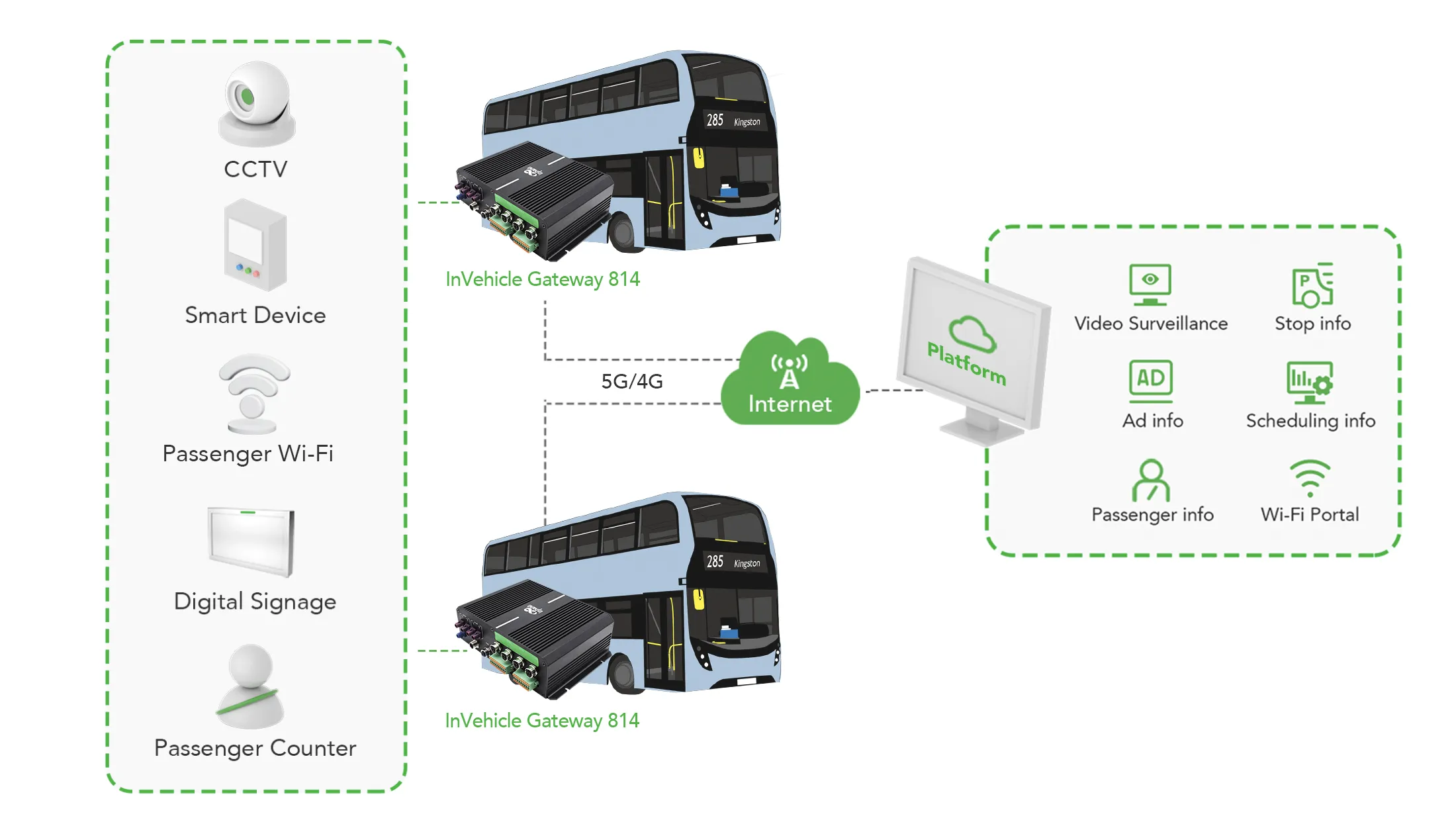
Fig. 1-1 VG814 Application
The device is available in VG814 Road (Bus) and VG814 Rail versions.
1.2 Packaging List
(Original document does not specify; to be supplemented)
1.3 LED Indicators
| Indicator | Status and Definition |
|---|---|
| System | Steady off — Powered off Steady red — System starting Steady blue — IGT not correctly installed Blink green — System operating normally Blink red — System faulty Blink blue — System upgrading |
| Cellular | Steady off — Dialup disabled Blink green — Dialup in progress Steady green — Dialup succeeded Blink red — Dialup failed (no module or SIM detected) |
| Signal | Steady off — No signal Steady red — Weak signal (≤ 9 asu) Steady blue — Moderate signal (10–19 asu) Steady green — Strong signal (≥ 20 asu) |
| GNSS | Steady off — GNSS disabled Blink green — Positioning in progress Steady green — Positioning completed |
| Wi-Fi 2.4G | AP: Off — Disabled; Blink green — Operating STA: Off — Disabled or no AP; Steady green — Wrong password; Blink green — AP associated |
| Wi-Fi 5G | AP: Off — Disabled; Blink blue — Operating STA: Off — Disabled or no AP; Steady blue — Wrong password; Blink blue — AP associated |
1.4 Restore to Factory Defaults
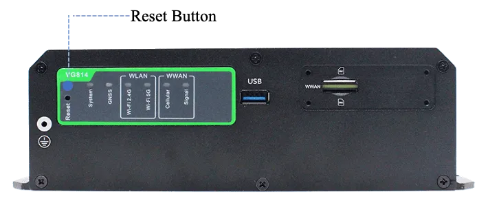
Fig. 1-2 Reset Button
- Power on the device and immediately press and hold the Reset button. After about 15 s, only the System indicator is steady red.
- When the System indicator turns off and becomes red again, immediately release the Reset button.
- When the System indicator turns off, press the Reset button (ensure it blinks red twice) and then release it. The device is restored to the default settings.
1.5 Default Settings
| No. | Function | Default Settings |
|---|---|---|
| 1 | Cellular | Enabled; dual-SIM disabled, SIM1 enabled |
| 2 | GNSS / Inertial navigation | Enabled |
| 3 | OBD | Enabled; CANbus baud rate and OBD protocol auto-detected |
| 4 | Wi-Fi | 2.4G/5G AP enabled; SSID VG814- or VG814-5G- + 6 digits; WPA2-PSK; password is last 8 digits of SN |
| 5 | Ethernet | 4 LAN ports enabled; IP 192.168.2.1; subnet 255.255.255.0; DHCP (Dynamic Host Configuration Protocol, can be understood as: the network's "automatic assigner" that assigns IP addresses and other parameters to connected devices) server enabled, pool 192.168.2.2–192.168.2.100 |
| 6 | Network access control | HTTP/HTTPS enabled on ports 80/443; Telnet/SSH disabled; cellular access allowed only over HTTPS |
| 7 | Username/Password | adm / 123456 |
| 8 | Power management | shutdown-delay 30; standby-mode 1; standby-check-interval 20; standby-voltage 90; standby-resume-voltage 105 |
| 9 | IO | Four digital output channels output at low level by default; pull-up resistor disabled for six digital input channels |
| 10 | Serial port | RS232/RS485: 9600 baud, 8 data bits, no parity, 1 stop bit |
1.6 Panel Interface
VG814 Road (Bus) Version
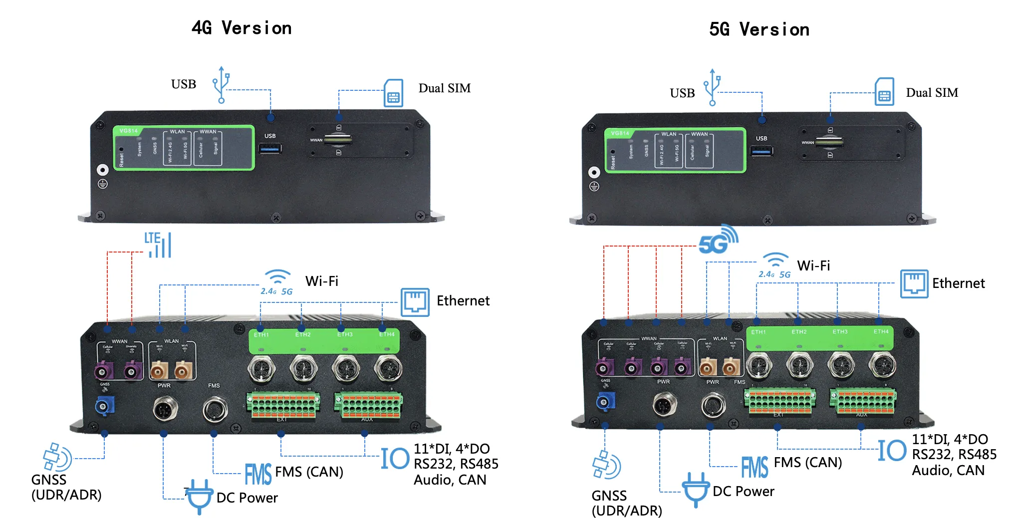
Fig. 1-3 VG814 Road (Bus) Antenna Panel
Antenna and SIM
| Item | Specification |
|---|---|
| GNSS Connector | FAKRA C-coded male |
| Wi-Fi Connector | FAKRA I-coded male |
| Cellular Connector | 4G: 2× FAKRA D-coded male; 5G: 4× FAKRA D-coded male |
| SIM | 2× Mini SIM 2FF |
Interface Info
| Item | Specification |
|---|---|
| Gigabit Ethernet | M12 X-Coded female |
| FMS | M12 A-Coded female |
| Power | M12 A-Coded male |
| ETX | 20-pin industrial segment |
| AUX | 18-pin industrial segment |
ETX 20PIN Definition
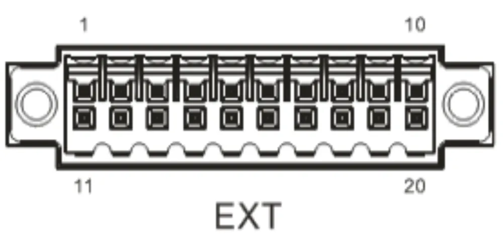
| PIN | 1 | 2 | 3 | 4 | 5 | 6 | 7 | 8 | 9 | 10 |
|---|---|---|---|---|---|---|---|---|---|---|
| Signal | GND | DO2 | DO4 | WHEELTICK | GND | RS232_RX1 | L-Channel | GND | CAN1_L | RS485_A |
| PIN | 11 | 12 | 13 | 14 | 15 | 16 | 17 | 18 | 19 | 20 |
| Signal | GND | DO3 | PPS | FWD | GND | RS232_TX1 | R-Channel | Mic In | CAN1_H | RS485_B |
AUX 18PIN Definition
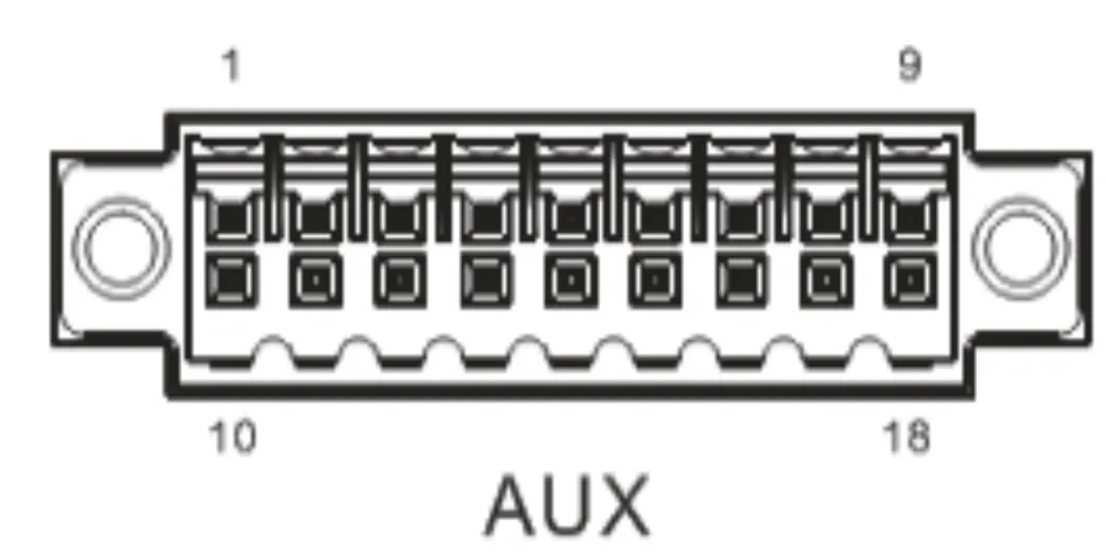
| PIN | 1 | 2 | 3 | 4 | 5 | 6 | 7 | 8 | 9 |
|---|---|---|---|---|---|---|---|---|---|
| Signal | DI1 | DI2 | DI3 | DI4 | DI5 | DI6 | DI7 | DI8 | GND |
| PIN | 10 | 11 | 12 | 13 | 14 | 15 | 16 | 17 | 18 |
| Signal | GND | GND | GND | GND | DI9 | DO1 | DI10 | DI11 | GND |
VG814 Rail Version
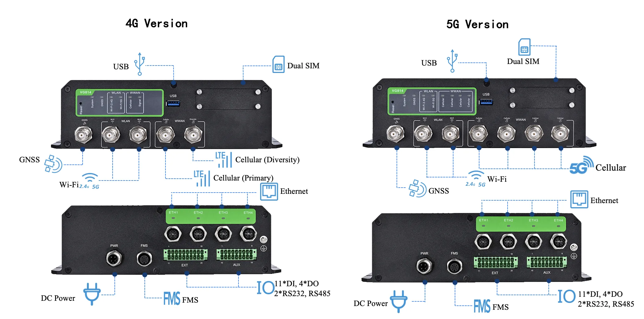
Fig. 1-4 VG814 Rail Antenna Panel
Antenna and SIM
| Item | Specification |
|---|---|
| GNSS Connector | TNC Female |
| Wi-Fi Connector | TNC Female |
| Cellular Connector | TNC Female |
| SIM | 2× Mini SIM 2FF |
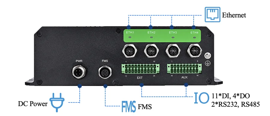
Fig. 1-5 VG814 Rail Interface Panel
Interface Info
| Item | Specification |
|---|---|
| Gigabit Ethernet | M12 X-Coded female |
| FMS | M12 A-Coded female |
| Power | M12 A-Coded male |
| ETX | 20-pin industrial segment |
| AUX | 18-pin industrial segment |
ETX 20PIN Definition (Rail)
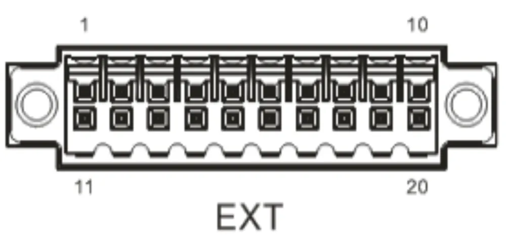
| PIN | 1 | 2 | 3 | 4 | 5 | 6 | 7 | 8 | 9 | 10 |
|---|---|---|---|---|---|---|---|---|---|---|
| Signal | GND | DO2 | DO4 | DO6 | GND | RS232_RX1 | RS232_RX2 | GND | CAN_L | RS485_A |
| PIN | 11 | 12 | 13 | 14 | 15 | 16 | 17 | 18 | 19 | 20 |
| Signal | GND | DO3 | DO5 | DO7 | GND | RS232_TX1 | RS232_TX2 | GND | CAN_H | RS485_B |
AUX 18PIN Definition (Rail)
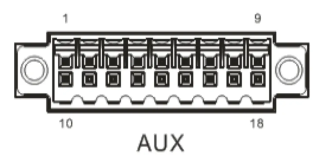
| PIN | 1 | 2 | 3 | 4 | 5 | 6 | 7 | 8 | 9 |
|---|---|---|---|---|---|---|---|---|---|
| Signal | DI1 | DI2 | DI3 | DI4 | DI5 | DI6 | DI7 | DI8 | GND |
| PIN | 10 | 11 | 12 | 13 | 14 | 15 | 16 | 17 | 18 |
| Signal | GND | GND | GND | GND | DI9 | DO1 | DI10 | DI11 | GND |
Power and FMS Connectors
VG814 Road/Bus and Rail versions share the same power and FMS connectors.
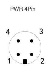
Fig. 1-6 Power Connector
| PWR PIN | Signal |
|---|---|
| 1 | VIN+ |
| 2 | IGT (ACC) |
| 3 | VIN- |
| 4 | NC |
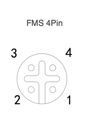
Fig. 1-7 FMS Connector
| FMS PIN | Signal |
|---|---|
| 1 | CAN_H |
| 2 | CAN_L |
| 3 | GND |
| 4 | NC |
Note: For office testing, connect the red V+ wire and white IGT wire to the positive pole of the DC power supply, and the black V- wire to the negative pole.
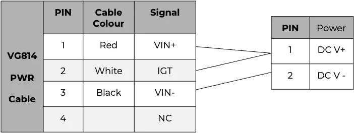
Fig. 1-8 Power Cable Connection
2. Installation and First Use
2.1 Environment Setup
- Insert the SIM card, connect the GNSS and cellular antennas, and connect the power supply and PC. Insert the diversity dialup antenna when the dialup card has poor signals. Connect the Wi-Fi antenna before logging in to the device.
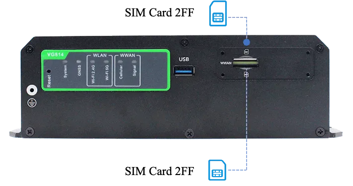
Fig. 2-1 Hardware Connection
Note: Before inserting or removing the SIM card, unplug the power cable; otherwise, the operation may cause data loss or damage the gateway.
- Assign an IP address to the PC on the same network segment as the gateway. Method 1: Enable the PC to obtain an IP automatically (recommended). Method 2: Configure a fixed IP: 192.168.2.2–192.168.2.254, subnet 255.255.255.0, gateway 192.168.2.1.
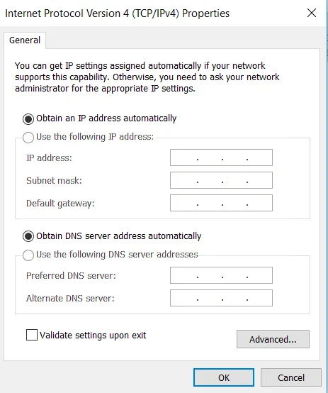
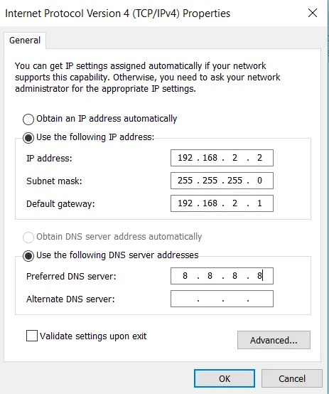
Fig. 2-2 Configure PC IP Address
- Open the browser, enter 192.168.2.1 in the address bar, and press Enter. Log in with the default username adm and password 123456 to access the web interface. If a blocking prompt is displayed, click "Advanced >> Continue".

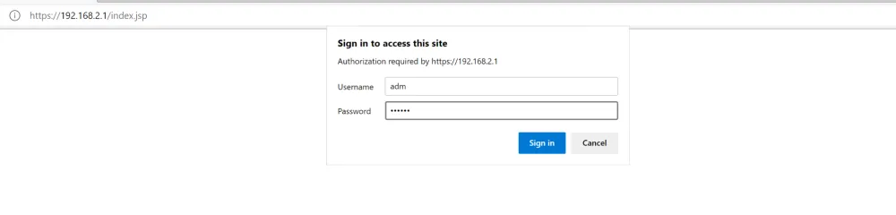
Fig. 2-3 Web Login
Method 3: Connect via Wi-Fi (see SSID and key on the nameplate). Enter 192.168.2.1 in the browser and log in.
2.2 Hardware Installation
The recommended installation position is in the air conditioning duct of the vehicle.
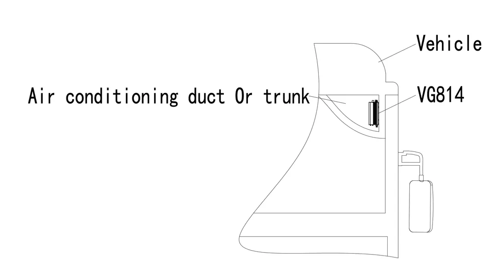
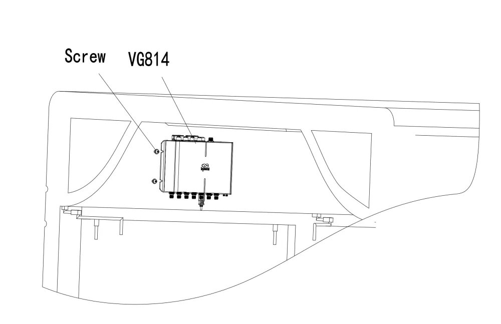
Fig. 2-4 Recommended Installation Position
3. Common Scenarios
3.1 Cellular Connection
Goal: Connect to the internet via cellular dialup.
Prerequisites: SIM card inserted, antennas connected, device powered on.
Est. time: ~5 min.
- Click "Network >> Cellular", check "Enable", and click Apply & Save. If the connection status is "Connected" and an IP address has been allocated, the SIM card has been connected to the network.
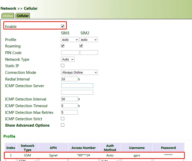
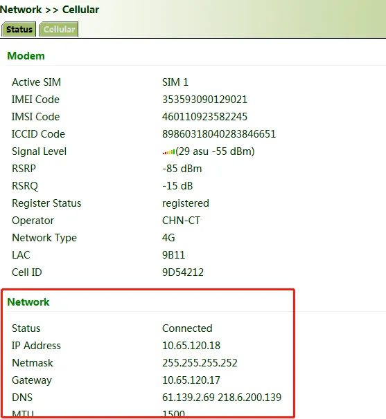
Fig. 3-1 Cellular Configuration
- Use the Ping tool to test connectivity. If there is data transmission, the device has been successfully connected to the network.
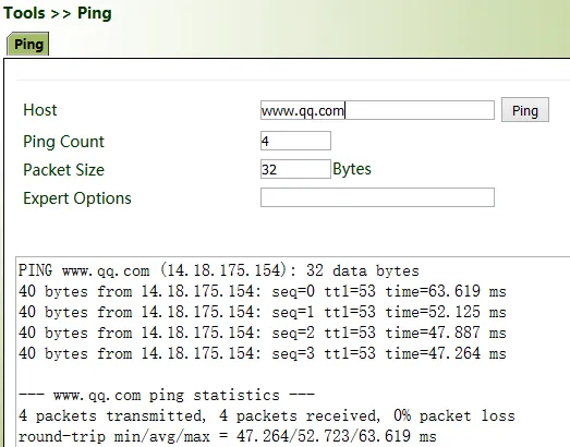
Fig. 3-2 Ping Test
- Enable the dual-SIM function when two SIM cards are used.
3.2 Wi-Fi Connection
Goal: Connect as a client to an on-site AP network.
Prerequisites: On-site Wi-Fi available.
Est. time: ~5 min.
-
Connect to the device via network cable or Wi-Fi (see SSID and key on the nameplate). Assign an IP to the PC and log in to the web page (see 2.1).
-
Click "Network >> Wi-Fi" and select Wi-Fi 2.4G or Wi-Fi 5G as a client. Enter the name, authentication method, and key of an available AP. Click Apply & Save.
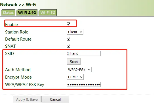
Fig. 3-3 Wi-Fi Client Configuration
- Check "Status". If the connection status is "Connected" and an IP address is obtained, the device has been successfully connected via Wi-Fi.
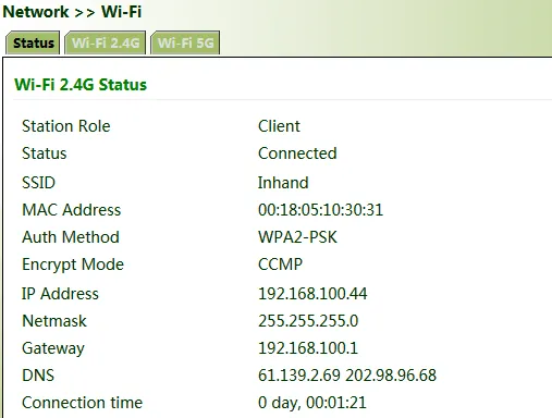
Fig. 3-4 Wi-Fi Status
4. Function Reference
This section summarizes the main functions of the VG814. Full parameter tables and configuration details are in the original document.
4.1 Network
Includes Cellular interface, Bridge port, VLAN port, ADSL Dialup (PPPoE), Wi-Fi, Loopback port, and Layer 2 Switch.
Entry: [ Network ]
4.2 OBD
On-board diagnostics (OBD) for vehicle data from CAN or LIN. CANbus baud rate and OBD protocol are auto-detected by default.
Entry: [ OBD ]
4.3 VPN
Supports IPSec, GRE, L2TP, and OpenVPN for secure tunnel connections.
Entry: [ VPN ]
4.4 Services
Includes DHCP Server/Client/Relay, DNS Server/Relay, DDNS, SMS, GPS (IP/Serial forwarding), QoS, and Traffic Control.
Entry: [ Services ]
4.5 Security
Includes firewall (ACL, NAT, MAC-IP Binding) and routing (Static, RIP, OSPF, BGP).
Entry: [ Firewall ], [ Routing ]
4.6 Link Backup
Includes SLA, Track, VRRP, and Interface Backup for link redundancy and failover.
Entry: [ Link Backup ]
4.7 Administration
Includes system status, user management, AAA, SNMP, alarm, system logs, upgrade, and reboot.
Entry: [ Administration ]
4.8 Diagnostic Tools
Includes Ping, Traceroute, Tcpdump, and Link Speed Test.
Entry: [ Administration >> Diagnostic Tools ]
See also: 4.1 Network | 4.3 VPN | 4.4 Services
5. Typical Applications
(Original document does not specify; to be supplemented)
Appendix A Troubleshooting
| Symptom | Possible Cause | Steps | Section |
|---|---|---|---|
| Cannot access web interface | PC not on same subnet | Configure PC IP: 192.168.2.2–254, gateway 192.168.2.1, subnet 255.255.255.0 | 2. Installation and First Use |
| Cellular dialup fails | SIM, antenna, APN | 1. Check SIM insertion and antenna installation 2. Configure APN for private-network card 3. Enable dual-SIM if using two SIMs |
3.1 Cellular Connection |
| Wi-Fi client fails | Wrong SSID/password | Check AP name, authentication method, and key | 3.2 Wi-Fi Connection |
| SIM card damage | Power on during insert/remove | Unplug power cable before inserting or removing SIM card | 2. Installation and First Use |
| System indicator steady blue | IGT not correctly installed | For office testing, connect IGT to V+ of power supply | 1.6 Panel Interface |
Appendix B Security Precautions
- Use the original power adapter to avoid damage from mismatched adapters.
- Do not install the device in strong electromagnetic interference environments or near high-power equipment.
- Ensure the operating environment meets the temperature and humidity requirements in the specification.
- Regularly inspect cables and replace damaged ones promptly.
- When cleaning, avoid spraying chemicals directly on the device. Use a soft cloth.
- Do not disassemble or modify the device; this may cause safety risks and void the warranty.
- For OBD installation: the power supply and OBD cable of the gateway shall be installed when the vehicle is off.
- During software upgrade, do not perform any operation on the web page; otherwise, the upgrade may be interrupted.
Note: Full descriptions of Network (Cellular, Bridge, VLAN, PPPoE, Wi-Fi, Loopback, Layer 2 Switch), OBD, VPN (IPsec, GRE, L2TP, OpenVPN), Services, Firewall, Routing, Link Backup, Administration, Diagnostic Tools, and M12 Ethernet connector definition, including screenshots and parameter tables, are in the original document. For more reference documents, see InVehicle-Docs.