Mo 62A Hardware Interface Description
This document summarizes Mo 62A from a hardware perspective: system structure, power and boot behavior, on-board peripheral interfaces, and the 40-pin expansion definition, with pointers to datasheets. The tone is descriptive; user-facing cautions are added where selection and cabling matter.
On this page
| Section | Summary |
|---|---|
| Connector quick reference | Find the physical interface by use case |
| System block diagram | Board-level functional blocks |
| Processor block diagram | SoC-side resource overview |
| Power | USB-C supply requirements and risks |
| Boot mode | Behavior with or without SD card |
| Storage | LPDDR4, Micro SD, EEPROM |
| On-board interfaces | Ethernet, USB, display, fan, audio, camera, wireless, RTC |
| Expansion interface (40-pin) | GPIO header pin table |
| LEDs and debug port | LED roles and serial debug header |
| Key components and references | Major ICs and local datasheet links |
Connector quick reference
Use this table to map a goal to the right connector; details are in the sections below.
| Goal | Suggested interface | Notes |
|---|---|---|
| Power the board | USB Type-C (5 V) | Use an adapter that can sustain 5 V at ≥ 3 A |
| Local display | Micro HDMI | Up to 1080p |
| Wired Ethernet | RJ45 Gigabit | PoE requires an add-on PoE expansion board; the on-board RJ45 alone is not a PoE powered-device interface |
| Keyboard, mouse, USB storage | 4 × USB 2.0 Type-A | USB 2.0 speed |
| Data to PC or shared USB (depends on image) | USB Type-C | Same connector as power; electrical roles in Power |
| MIPI camera (e.g. IMX219 class) | 22-pin FPC CSI | Raspberry Pi–compatible mechanical footprint; MIPI CSI-2 |
| Headset or microphone | 3.5 mm 4-pole jack | Microphone input included |
| Better Wi-Fi / Bluetooth | On-module radio + U.FL antenna | Without an antenna, RF performance is usually much worse |
| Sensors, buses, GPIO | 40-pin header | Mostly 3.3 V GPIO by default; pin list in Expansion interface (40-pin) |
| Active cooling | 4-pin PWM fan | 1.0 mm pitch connector |
| RTC backup | RTC + external coin cell holder | Battery type in the RTC subsection |
| Headless bring-up / serial login | 3-pin debug header (UART) | Boot and console output; 115200 8N1 |
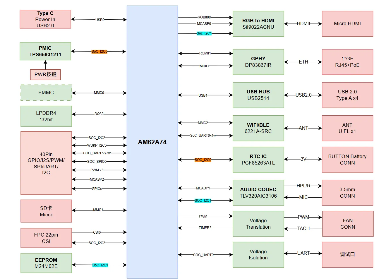
System block diagram
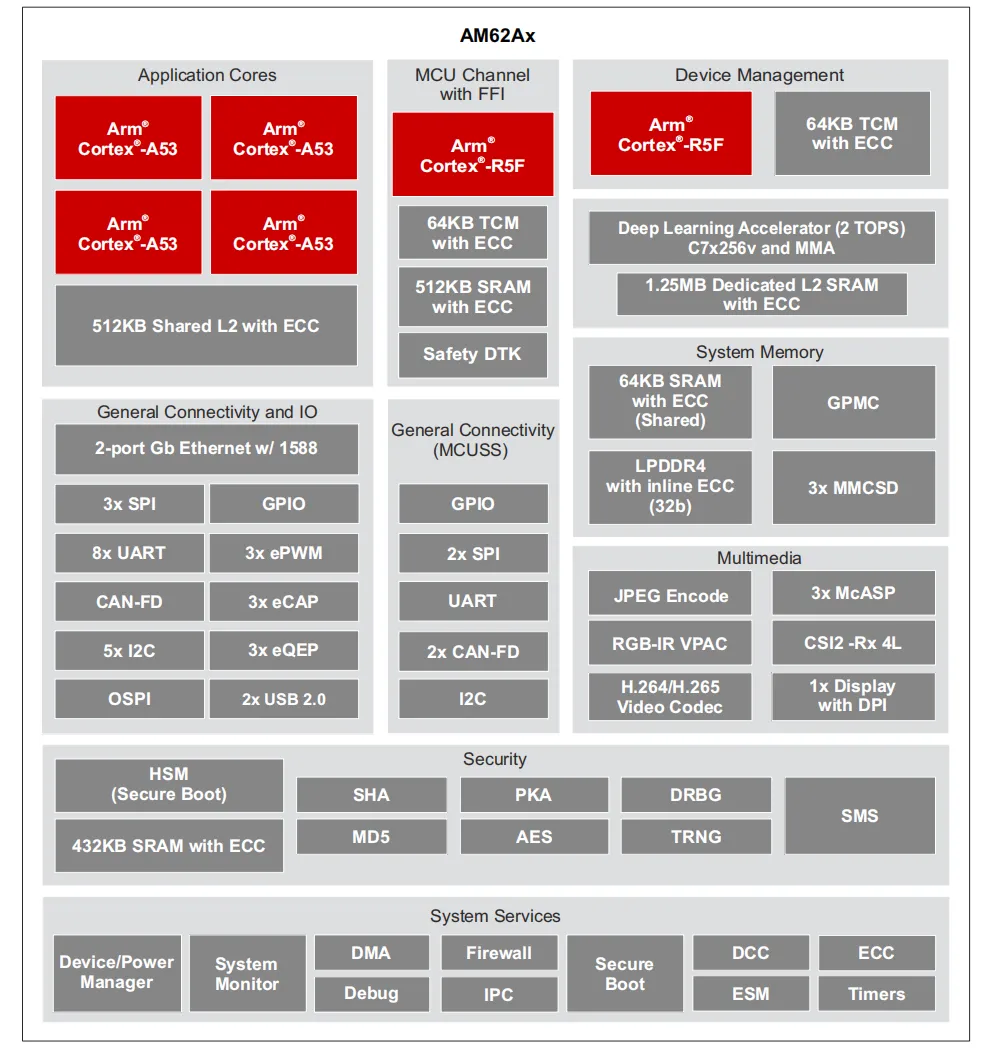
Processor block diagram
Power
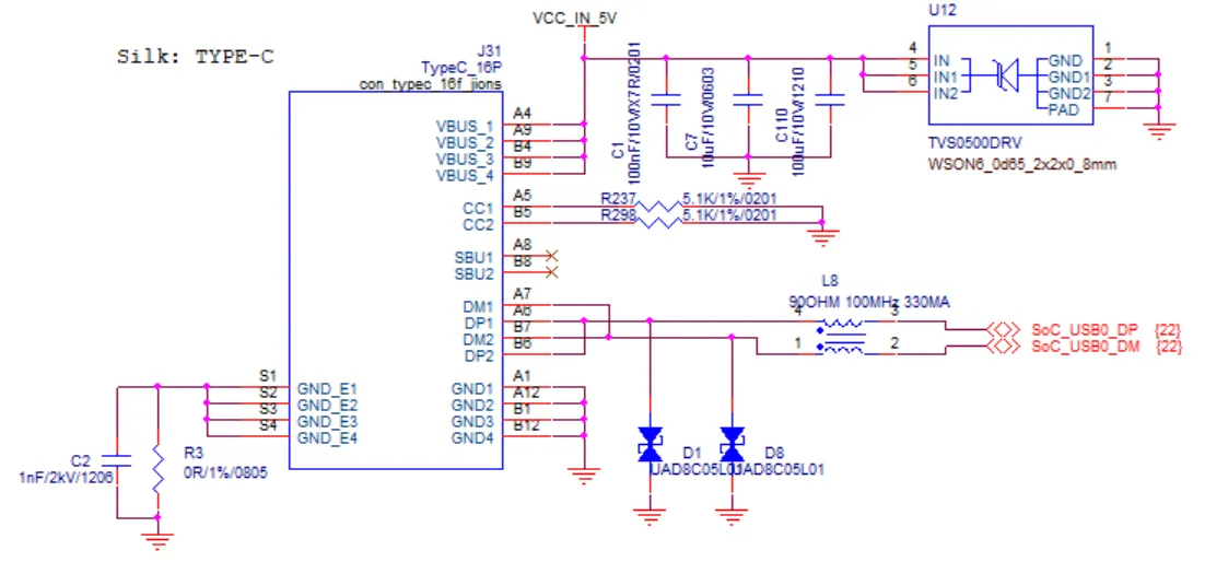
USB-C power input
Mo 62A takes power through USB-C. On the connector side, 5.1 kΩ and related configuration mark the device as a power sink (Sink / UFP); negotiation may settle on a lower USB-C current tier by default. Stable operation needs an external adapter that can deliver about 3 A continuously at 5 V.
Long-term use at 5 V with insufficient current can cause brownouts, failed storage writes, or connector heating. Check that the adapter’s 5 V rated current is ≥ 3 A and use quality cabling.
Boot mode
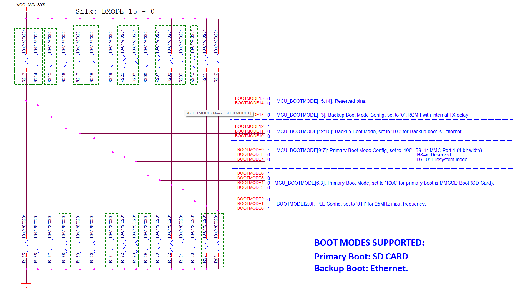
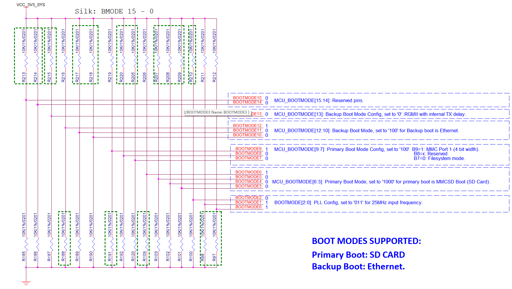
By default the SoC boots from Micro SD (MMC). If no SD card is inserted, the SoC BootROM attempts paths such as Ethernet (exact behavior depends on the current Boot ROM and strap design). In typical use, a programmed SD card is the boot medium.
Storage
LPDDR4
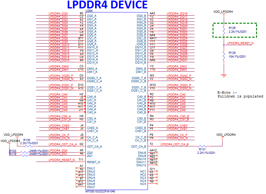
On-board ×32 LPDDR4 main memory. Common buildouts include 4 GB, with 2 GB and 8 GB variants depending on BOM and ordering.
Micro SD card
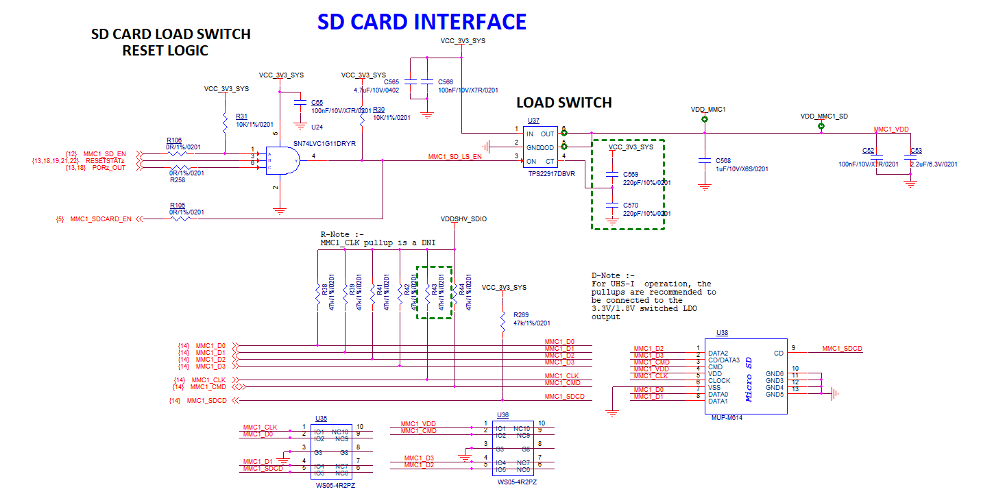
Micro SD is the main boot and bulk storage interface, wired to MMC1 on the AM62A74.
EEPROM
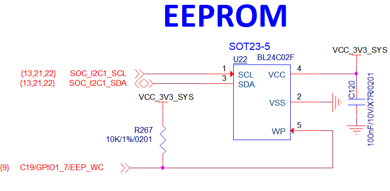
On-board BL24C02 (2 kbit) I²C EEPROM stores board-level and production-related identifiers that are read rarely or at low write frequency.
On-board interfaces
Gigabit Ethernet
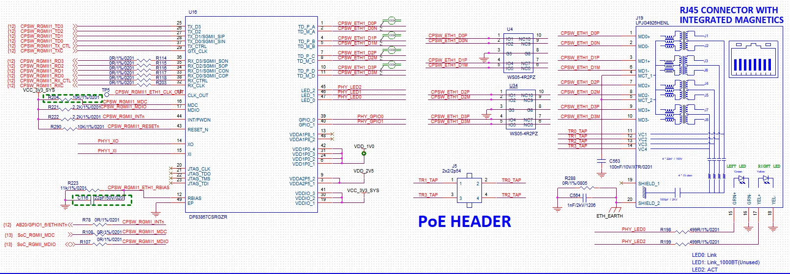
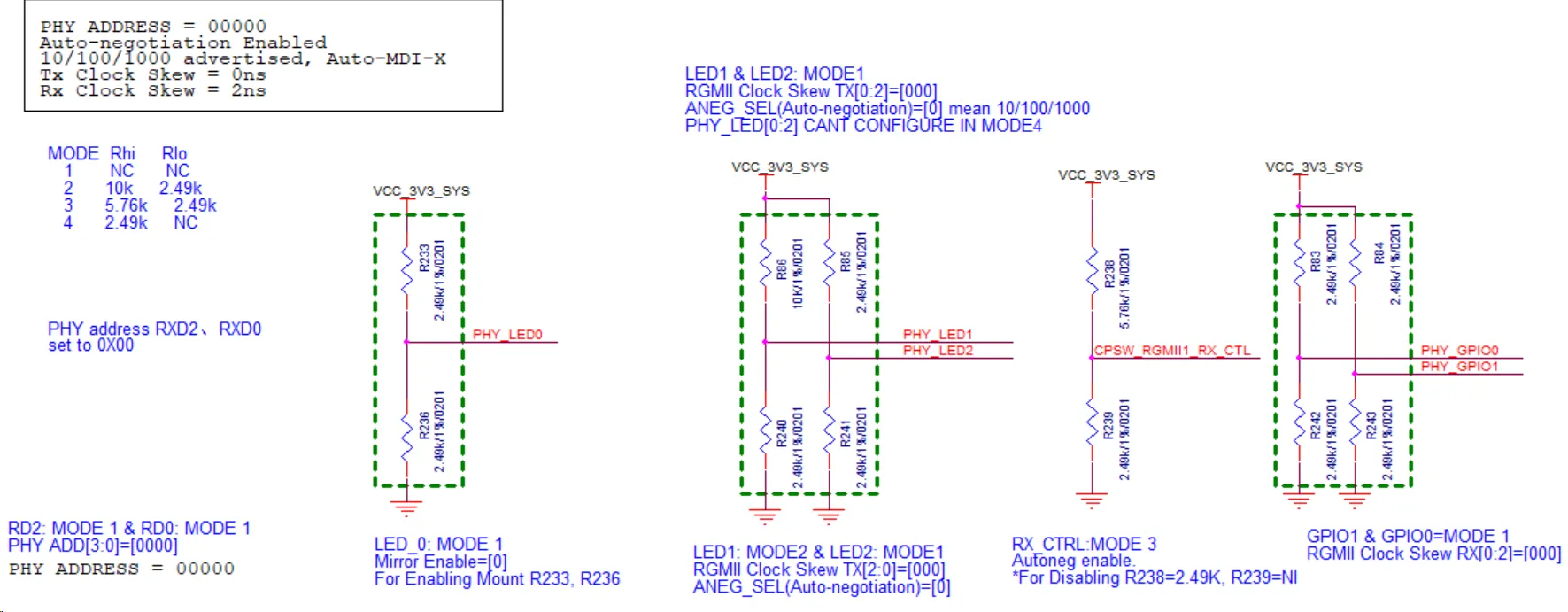
One Gigabit RJ45 port with 10/100/1000 Mbps auto-negotiation. PoE powered-device operation requires a PoE expansion board or similar add-on, not the RJ45 physical interface alone.
USB
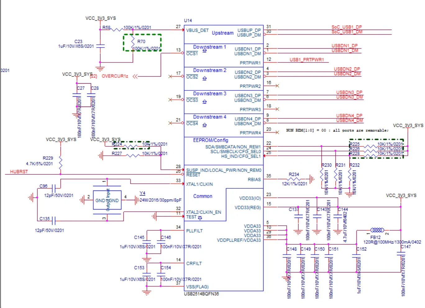
- 4 × USB 2.0 Type-A: standard USB devices such as keyboard, mouse, or flash drive.
- 1 × USB Type-C: shares the connector with power; the data path is USB 2.0 class (same generation as Type-A). Composite behavior follows implementation and system policy.
Micro HDMI
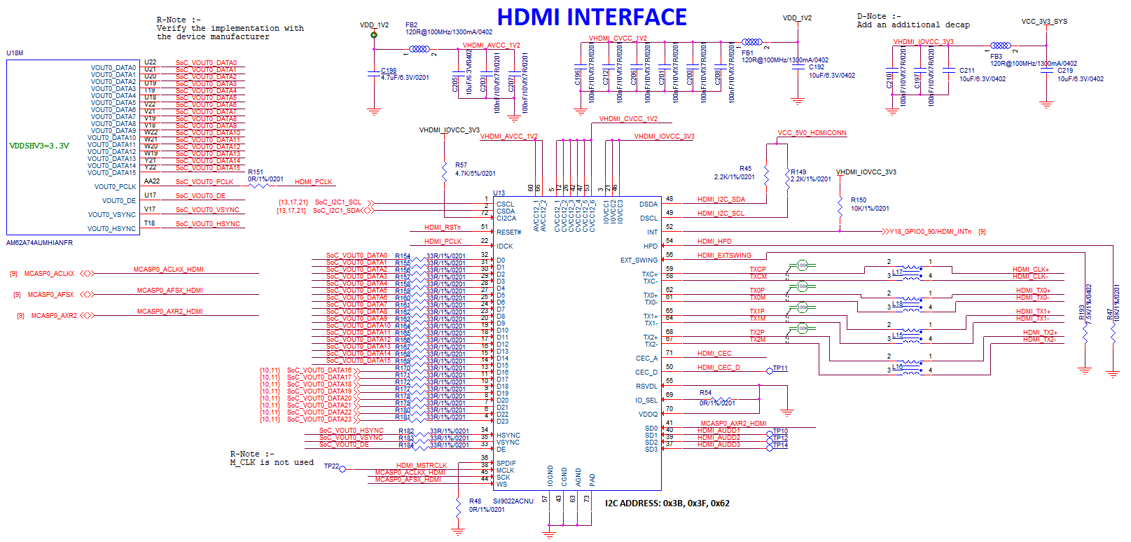
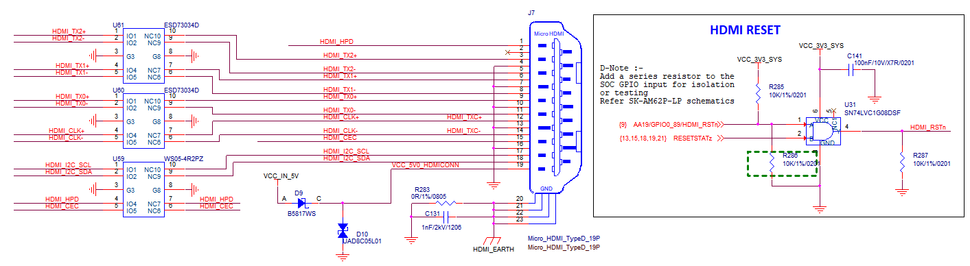
1 × Micro HDMI for an external display, up to 1080p. Video goes through a Lattice SiI9022A transmitter that converts parallel RGB plus McASP0-related audio to HDMI; mapping is RGB888 on a 24-bit bus.
Fan connector
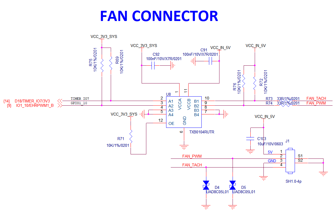
4-pin, 1.0 mm pitch fan connector with PWM speed control and tach feedback (exact pinout per silkscreen and schematic) for an active cooler under sustained load.
Headphone jack
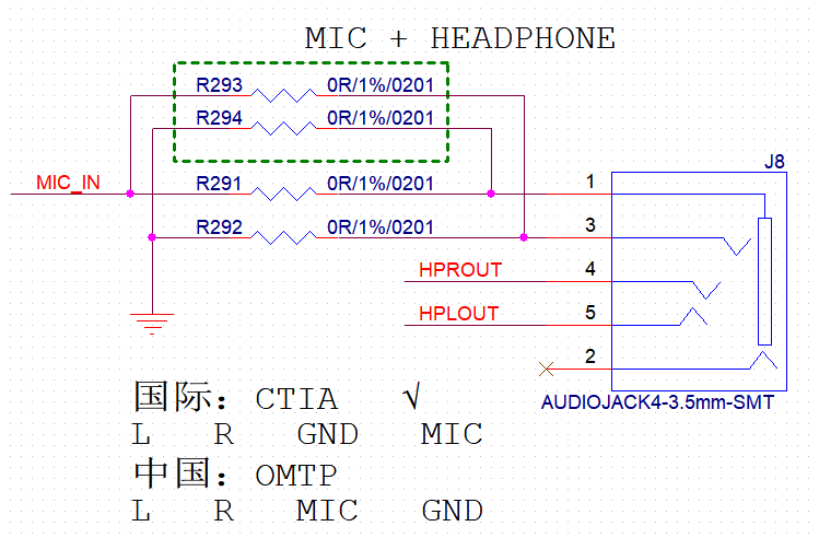
4-pole 3.5 mm jack for headphone output and microphone input, compatible with common mobile-style headsets.
CSI camera interface
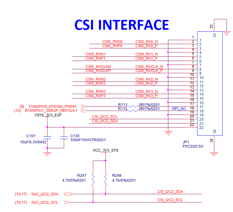
One CSI port with an FPC connector that matches the common Raspberry Pi module footprint. The AM62A74 side supports MIPI CSI-2 v1.3 and MIPI D-PHY 1.2, 4 lanes, up to about 2.5 Gbps per lane; the standard allows up to 16 virtual channels (subject to firmware and sensor capability).
Wi-Fi and Bluetooth
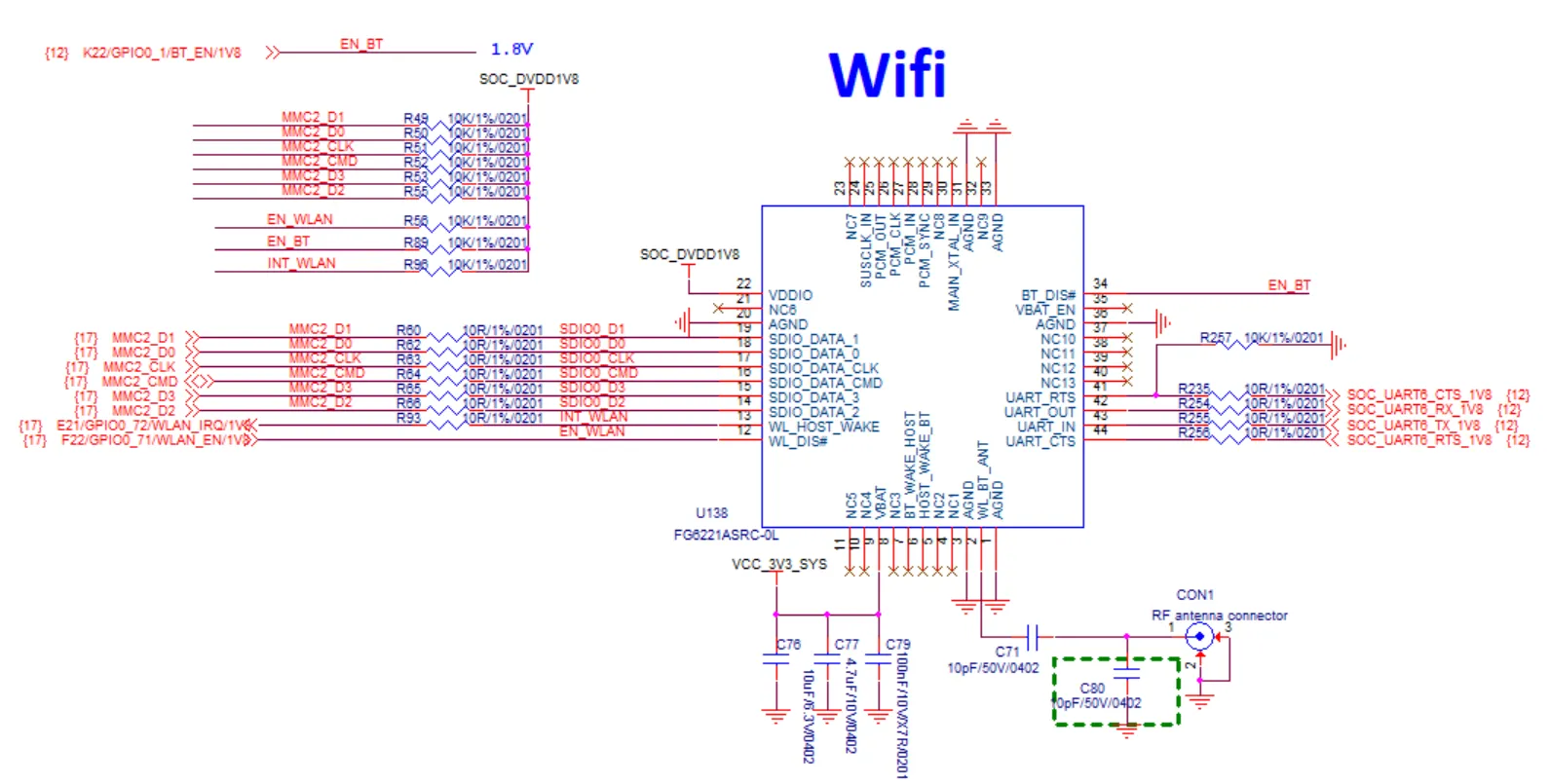
Wireless uses FG6221ASRC (Fn-Link and equivalent vendors), with IEEE 802.11 a/b/g/n/ac and BLE 4.2. Wi-Fi MAC/baseband connects over SDIO; Bluetooth uses UART.
An U.FL antenna connector sits near the module. Use a 2.4 GHz / 5 GHz (and Bluetooth) antenna with matching specs; otherwise range and throughput often drop sharply.
RTC
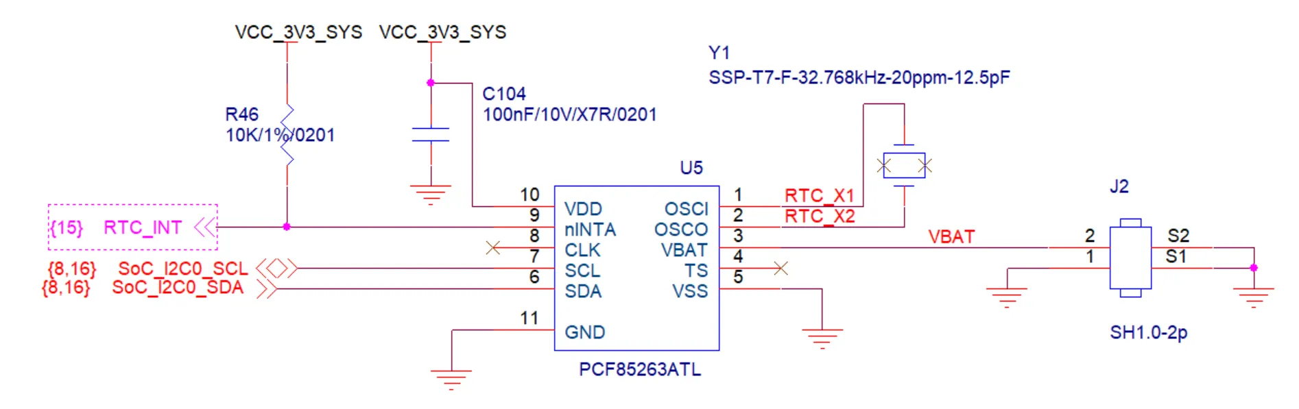
I²C RTC on board; an external coin cell can keep time when main power is off (holder and recommended part number per silkscreen and BOM—often CR1220 class).
Expansion interface (40-pin)
The 40-pin header is primarily 3.3 V GPIO and can be multiplexed in software or via the device tree to I²C, SPI, UART, PWM, and other functions per the AM62A7 mux table. Do not connect 5 V TTL directly to GPIO pins.
| Function2 | Function1 | Pin# | Pin# | Function1 | Function2 |
|---|---|---|---|---|---|
| 3.3V | 1 | 2 | 5.0V | ||
| WKUP_I2C0_SDA | E13/MCU_GPIO0_20 | 3 | 4 | 5.0V | |
| WKUP_I2C0_SCL | D13/MCU_GPIO0_19 | 5 | 6 | GND | |
| AUDIO_EXT_REFCLK1 | K17/GPIO0_39 | 7 | 8 | C18/GPIO1_25 | UART5_TXD |
| GND | 9 | 10 | B17/GPIO1_24 | UART5_RXD | |
| C15/GPIO1_23 | 11 | 12 | W17/GPIO1_0 | MCASP2_ACLKX_BUF | |
| M21/GPIO0_42 | 13 | 14 | GND | ||
| F14/GPIO1_22 | 15 | 16 | R17/GPIO0_38 | ||
| 3V3 | 17 | 18 | K18/GPIO0_40 | ||
| EXP_SPI0_D0 | B15/GPIO1_18 | 19 | 20 | GND | |
| EXP_SPI0_D1 | E15/GPIO1_19 | 21 | 22 | G20/GPIO0_14 | |
| EXP_SPI0_CLK | A17/GPIO1_17 | 23 | 24 | D16/GPIO1_15 | EXP_SPI0_CS0 |
| GND | 25 | 26 | C16/GPIO1_16 | EXP_SPI0_CS1 | |
| SoC_I2C2_SDA | 27 | 28 | SoC_I2C2_SCL | ||
| M18/GPIO0_36 | 29 | 30 | GND | ||
| L17/GPIO0_33 | 31 | 32 | A21/GPIO1_14 | IO1_14/EHRPWM0_B | |
| IO1_13/EHRPWM0_A | B21/GPIO1_13 | 33 | 34 | GND | |
| MCASP2_AFSX_BUF | AA18/GPIO0_91 | 35 | 36 | B18/GPIO1_09 | IO1_09/EHRPWM1_A |
| M19/GPIO0_41 | 37 | 38 | AB21/GPIO1_5 | MCASP2_AXR0_BUF | |
| GND | 39 | 40 | AA20/GPIO1_2 | MCASP2_AXR1_BUF |
Note: Pins 27 and 28 are SoC I2C2, often tied to the CSI sensor configuration. Avoid bus conflicts with the camera when designing expansions. For GPIO versus bus muxing in software, see the Quick Start Guide or BSP device-tree documentation.
LEDs and debug port
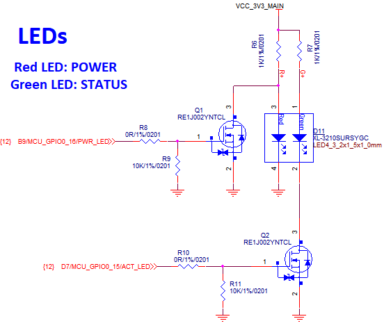
The board has red / green dual-color LEDs for power and activity/status (exact blink patterns depend on implementation and services).
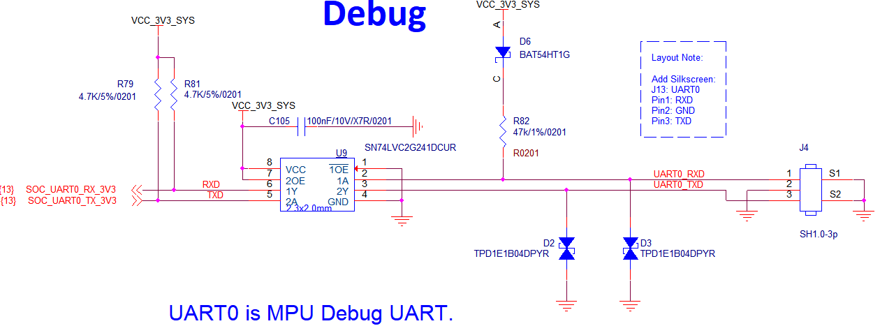
UART debug is on a 3-pin header (typically JST-style) for boot logs and serial console login. When using a USB serial adapter, match TX/RX/GND and 115200 8N1, no flow control.
Key components and references
| Component | Part / variant | Datasheet / manual |
|---|---|---|
| Applications processor | AM62A family AM62A74AUMHIANFR | AM62A74 datasheet |
| PMIC | TPS65931211RWE | TPS6593-Q1 |
| Ethernet PHY | DP83867CSRGZR | DP83867CS |
| RTC | PCF85263ATL | PCF85263ATL |
| EEPROM | BL24C02F | BL24C02F |
| HDMI transmitter | SiI9022A | SiI9022A |
| Audio codec | tlv320aic3106 | tlv320aic3106 |
| Wi-Fi / BLE module | FG6221ASRC | FG6221ASRC |