IG502 — IEC 60870-5-101 to IEC 60870-5-104 Conversion Configuration Guide¶
Product Model: IG502 (InGateway 502)¶
1. Document Information¶
| Item | Value |
|---|---|
| Product | InHand IG502 Edge Gateway |
| Application | IEC 60870-5-101 (serial) ↔ IEC 60870-5-104 (TCP/IP) protocol conversion |
| Typical use cases | Smart grid, distribution automation, substation retrofit, renewable plants, water / gas SCADA |
2. Reference Network¶
The reference setup used throughout this manual:
- PC 1 — runs an IEC 60870-5-101 server simulator (acts as the field RTU/IED). Wired to the IG502's RS-485 port.
- IG502 — the gateway. Acts as IEC 101 client on RS-485 and IEC 104 server on the LAN port.
- PC 2 — runs an IEC 60870-5-104 client simulator (acts as the SCADA master). Wired to the IG502's LAN port.
Test goal: the IEC 104 client on PC 2 reads the data points generated by the IEC 101 server on PC 1, end-to-end through the IG502.
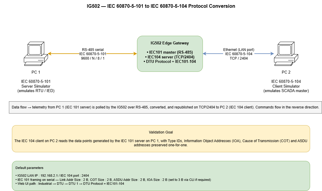
In production deployments, PC 1 is replaced by the real RTU/IED on RS-485, and PC 2 is replaced by the real SCADA front-end on Ethernet or cellular.
3. Hardware Overview¶
3.1 IG502 at a Glance¶
- Power input: DC 9–36 V, reverse-polarity protected
- Ethernet: 2× RJ45 (configurable WAN / LAN)
- Serial: RS-232 and / or RS-485 (model dependent)
- Wireless: 4G / 5G / Wi-Fi (model dependent)
- Indicators: Power, Status, Cellular, Signal, Wi-Fi
- Reset button: long-press for factory default
- Mounting: DIN rail / wall
3.2 Wiring for This Application¶
| Port | Connect to | Notes |
|---|---|---|
| Power | DC 9–36 V supply | Observe polarity |
| RS-485 (A / B) | IEC 101 device's RS-485 (A / B) | Common ground; daisy-chain if multi-drop; 120 Ω termination at the bus ends |
| LAN / WAN (RJ45) | SCADA network switch / PC | LAN by default; can be re-roled to WAN |
| Cellular antenna (MAIN) | 4G / 5G antenna | If cellular backhaul is used |
| GND | Cabinet earth | Mandatory for substation / outdoor installation |
4. Factory Defaults¶
| Parameter | Default |
|---|---|
| LAN IP | 192.168.2.1 |
| Subnet Mask | 255.255.255.0 |
| Web username | adm |
| Web password | 123456 (later batches: random password — see device label) |
| Telnet / SSH | Disabled by default |
5. Pre-Installation Checklist¶
- Set the PC's NIC to the IG502's LAN subnet (e.g., 192.168.2.100 / 255.255.255.0).
- Use an Ethernet cable to connect the PC to the IG502 LAN port.
- Power the IG502; wait until the Status LED is steady.
- Open a modern browser (Chrome / Edge / Firefox) and navigate to
http://192.168.2.1. - Log in with
adm / 123456(or the label password).
6. Network Configuration (recap)¶
The full LAN, WAN and cellular configuration procedures follow the standard IG502 user guide. Only the items relevant to the IEC conversion are highlighted below.
- LAN IP: keep on the same subnet as the SCADA front-end (PC 2 in this manual). Default 192.168.2.1 is used in the worked example.
- Cellular (if used as uplink): insert SIM with the device powered OFF; configure APN under Network → Cellular. Confirm signal LED is green (RSSI 21–30).
- Firewall / port forwarding: ensure inbound TCP 2404 is permitted from the SCADA master to the IG502.
For the basic web flow (LAN IP change, cellular dial-up, signal indicator), see the existing Configuration Manual in this folder.
7. IEC 101 ↔ IEC 104 Conversion — Step-by-Step¶
This is the core of the manual. The IG502 implements the conversion through its DTU 1 module under Industrial → DTU.
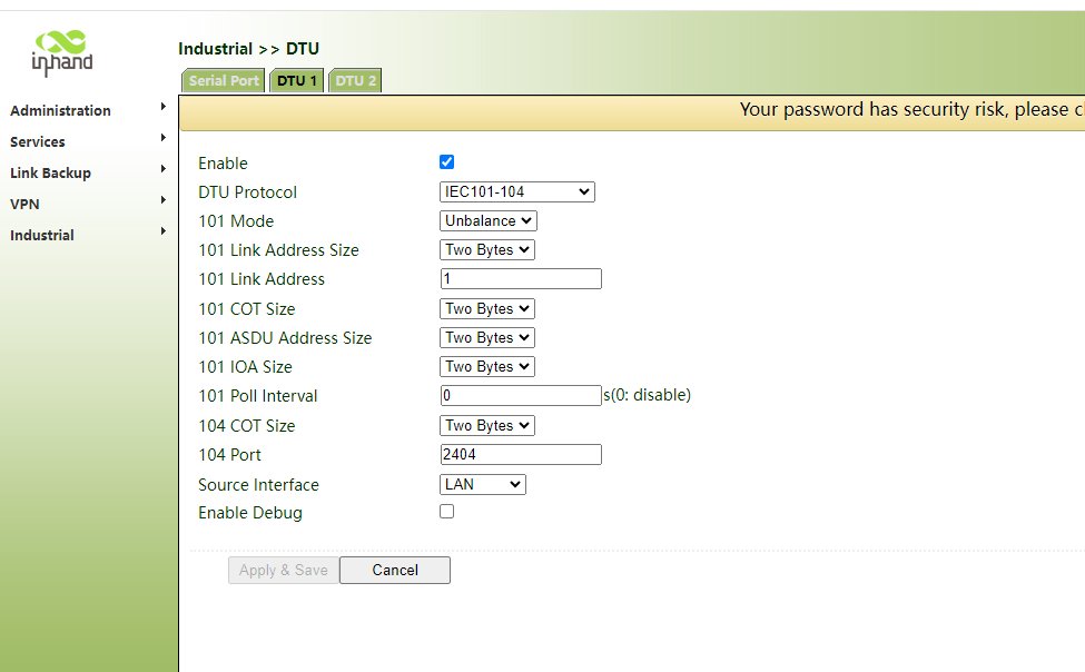
7.1 Enable the DTU and Choose the IEC101-104 Protocol¶
- Log in to the IG502 Web UI.
- Navigate to Industrial → DTU → DTU 1.
- Tick Enable.
- Set DTU Protocol to
IEC101-104.
7.2 Configure the IEC 101 (Serial) Side¶
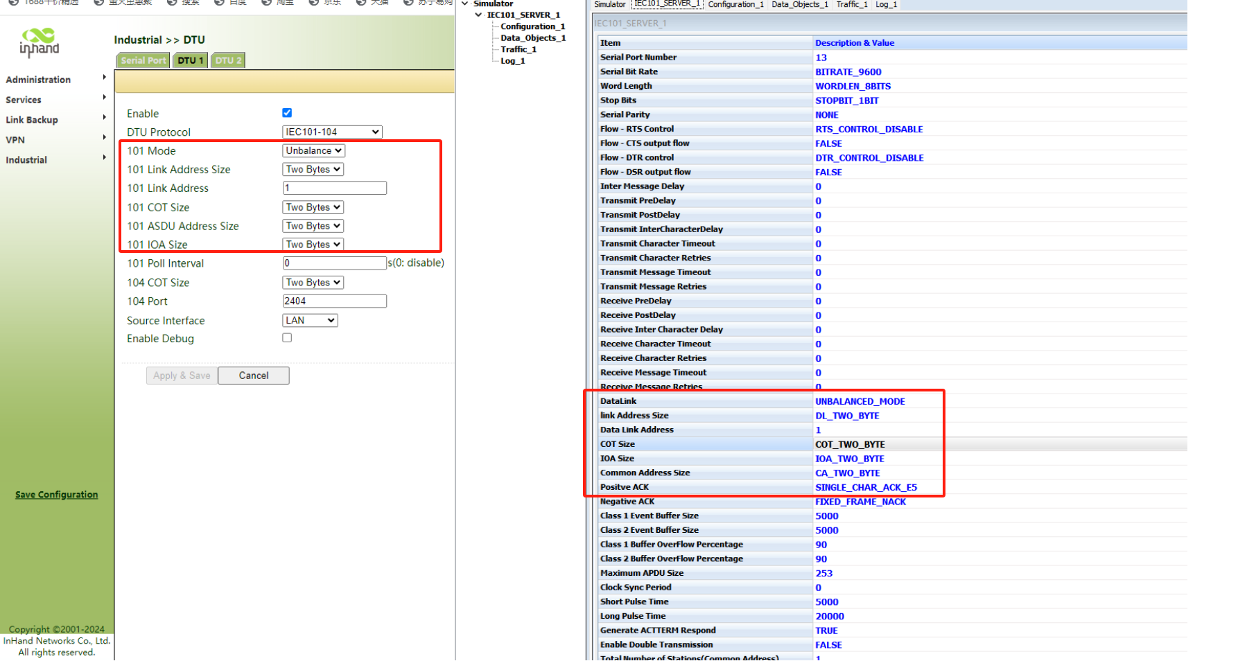
These parameters MUST match the IEC 101 outstation (or simulator) on the serial bus.
| Field | Recommended / Default | Description |
|---|---|---|
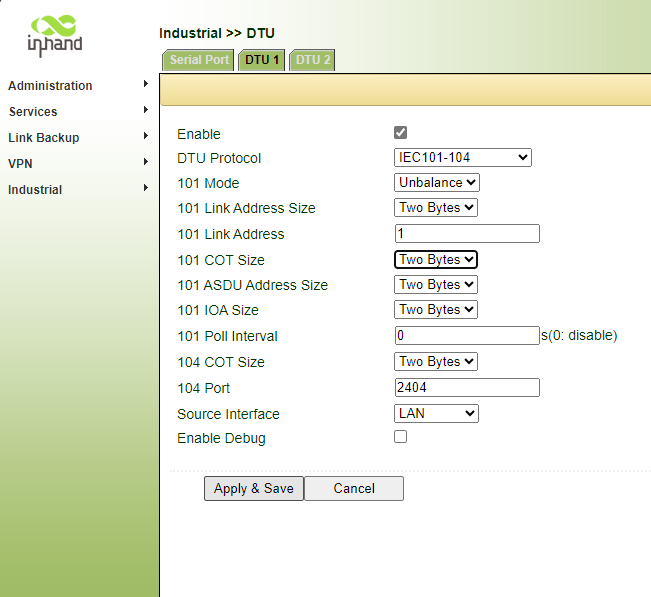
| 101 Mode | Unbalance | Use Unbalance for typical multi-drop RS-485 polled topologies; use Balance for point-to-point. Must match the device. |
| 101 Link Address Size | Two Bytes | Most field devices use 2 bytes; some legacy RTUs use 1 byte. Must match. |
| 101 Link Address | 1 | The slave's link address. Must match the device. |
| 101 COT Size | Two Bytes | Cause-of-transmission size. Typically 2 bytes for IEC 101. |
| 101 ASDU Address Size | Two Bytes | Common ASDU address (station address) length. |
| 101 IOA Size | Two Bytes | Information Object Address size. Web UI offers One/Two bytes. If three bytes are required, see §7.6 below. |
| 101 Poll Interval | 0 (disable) or 1–60 s | 0 means do not generate background polls; rely on spontaneous data. Set a value (e.g. 5–10 s) to actively poll. |
Serial line parameters (baud, parity, data bits, stop bits) are set under the Serial Port sub-tab (defaults: 9600, N, 8, 1) and must match the wired bus.
7.3 Configure the IEC 104 (TCP) Side¶
| Field | Recommended / Default | Description |
|---|---|---|
| 104 COT Size | Two Bytes | Standard IEC 104. |
| 104 Port | 2404 | Standard IEC 104 listening port. |
| Source Interface | LAN | The interface on which the IG502 listens for IEC 104 clients. Use LAN, WAN or Cellular as appropriate. |
| Enable Debug | Off (production) / On (commissioning) | Enables verbose DTU logs accessible via the log page or SSH. |
7.4 Apply and Save¶
Click Apply & Save at the bottom of the page. The IG502 restarts the DTU module; no full reboot is required.
7.5 Verify with Simulators (recommended for commissioning)¶
On PC 1 — IEC 101 server simulator:
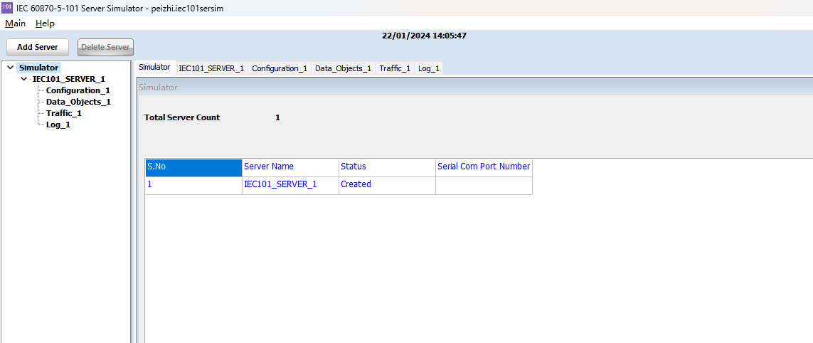
Set the framing sizes on the simulator to match the IG502 exactly (Link Address, COT, ASDU, IOA):
Add the data objects to publish — single point, double point, step position, bitstring, measured float, single / double command, set-point command:
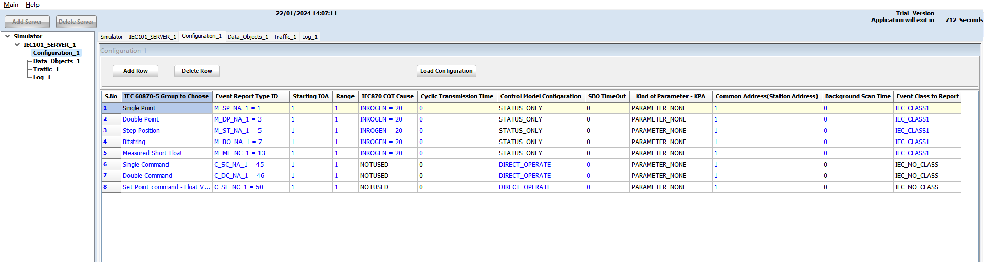
On PC 2 — IEC 104 client simulator:
Point the client at the IG502 LAN IP on port 2404:
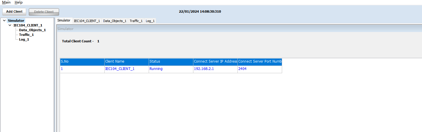
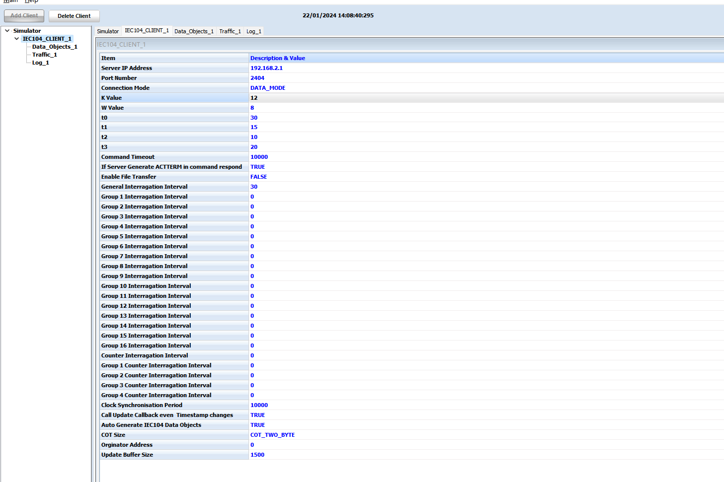
Confirm K/W timers and command timeout match your SCADA standard (defaults shown below work for most setups):
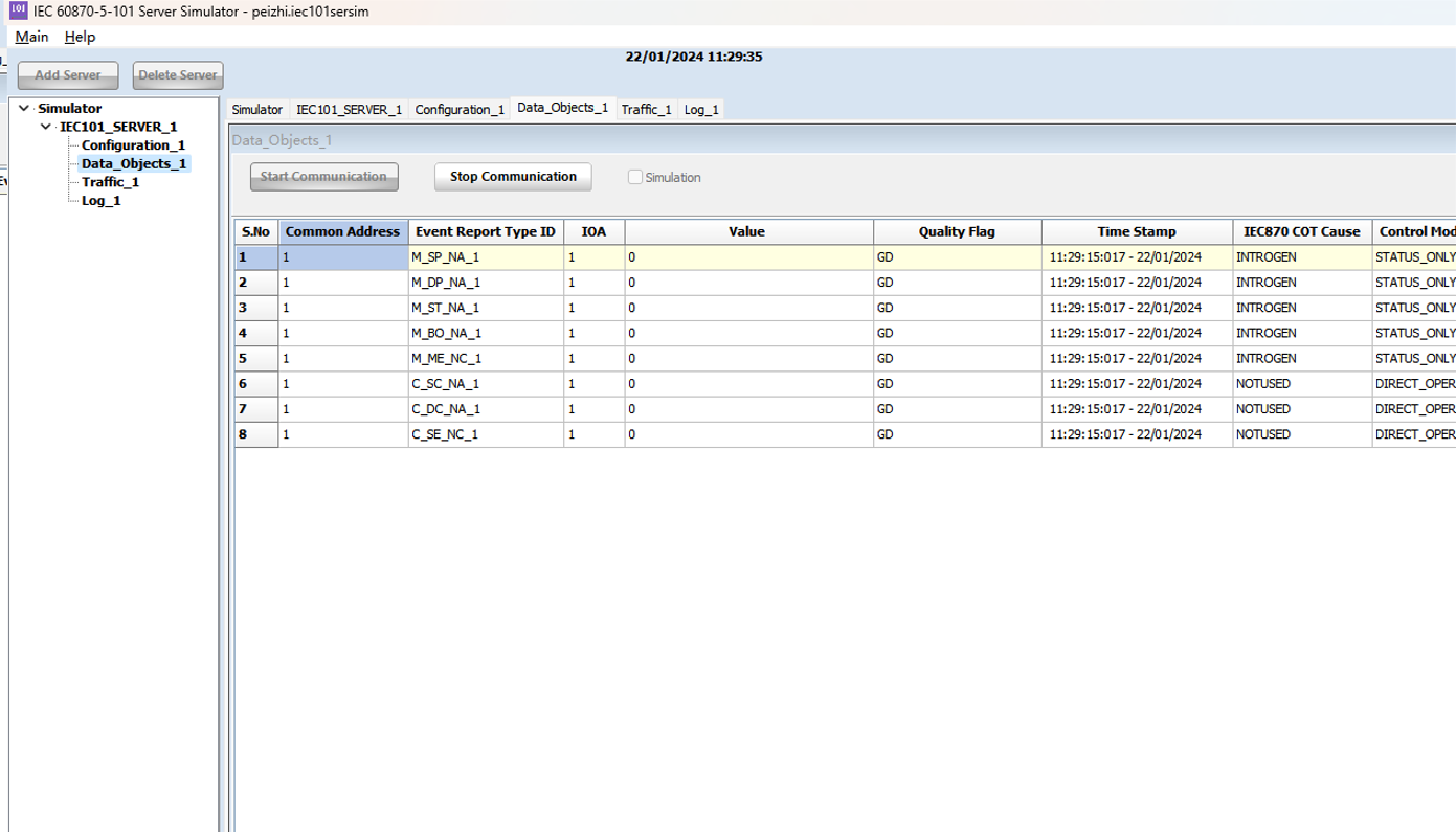
Expected result: every object configured on the IEC 101 side appears on the IEC 104 side with the correct Type ID, COT, value, quality flag (GD) and a fresh timestamp.
7.6 Optional — Set IEC 101 IOA Size to 3 Bytes (CLI override)¶
The Web UI lists One Byte / Two Bytes for IOA size. If a field device requires 3-byte IOA on the IEC 101 side, the value must be set from the CLI by editing the DTU configuration file.
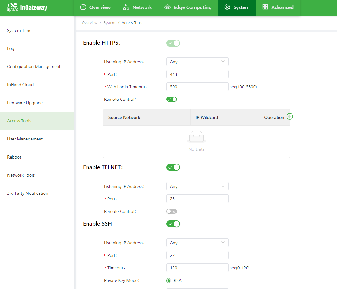
Step 1. Enable Telnet (or SSH) on the IG502.
Navigate to System → Access Tools and turn on Telnet (or SSH). Apply.
Step 2. Apply the configuration.
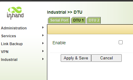
Step 3. Temporarily disable the DTU 1 instance.
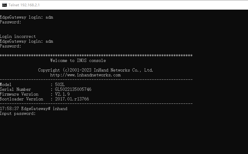
Step 4. Open a Telnet session to the IG502 (telnet 192.168.2.1) and log in with adm and the standard password; the second prompt asks for the privileged password (default inhand).
Step 5. Edit the DTU configuration file:
Find the line iec101_ioa_len and change its value to 3:
Save and quit (:wq).
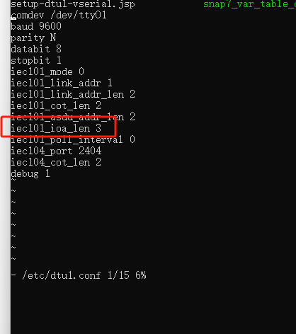
Step 6. Launch the IEC 10x service with the modified file:
The DTU now runs with a 3-byte IOA on the 101 side while keeping the standard 3-byte IOA on the 104 side.
⚠️ Note: if you re-enable DTU 1 from the Web UI later, the GUI will overwrite
/etc/dtu1.conf. Re-apply Steps 3–6 after any UI change to keep the 3-byte IOA setting.
8. Verification Checklist¶
Before leaving a site, confirm:
- The IG502 Status LED is steady; Signal LED is green if cellular is used.
- DTU 1 page shows
Enabledand protocolIEC101-104. - Framing parameters (Link Address, COT, ASDU, IOA) match the field device.
- On the IG502, traffic counters or debug log show successful IEC 101 polls / replies.
- The SCADA master station can open a TCP/2404 session to the IG502 and issues a
STARTDT act/ receivesSTARTDT con. - General interrogation returns all expected data objects with correct values and quality flags.
- Command (C_SC, C_DC, C_SE) round-trips reach the IEC 101 device and return
ActCon+ActTerm.
9. Troubleshooting¶
| Symptom | Likely Cause | Action |
|---|---|---|
| No data appears in the SCADA master | Framing mismatch (Link/COT/ASDU/IOA size or address) | Re-check §7.2 values against the field device documentation |
| Data appears but with wrong values / shifted IOA | IOA size mismatch | Verify §7.2; if 3-byte IOA is required, apply §7.6 |
| IEC 104 session opens then drops every few seconds | t1 / t2 / t3 / W / K mismatch, or NAT idling | Align timers between master and IG502; disable aggressive NAT timeouts on intermediate firewalls |
| No serial activity at all | Wrong COM port, baud / parity / stop bits, A/B swap on RS-485 | Confirm wiring and serial parameters under Industrial → DTU → Serial Port |
| SCADA cannot reach 2404 | Firewall / VPN routing | Allow inbound TCP 2404 to the IG502; verify with telnet <IG502_IP> 2404 from the SCADA host |
| 4G dial-up fails | SIM not seated, wrong APN, weak signal | Re-seat SIM with power off, set APN, check antenna |
| Forgotten Web password | — | Long-press the reset button to restore defaults; reconfigure |
10. Safety Notes¶
- Ensure the cabinet is reliably earthed in substation / outdoor deployments.
- Do not hot-swap the serial connector while the device is energized.
- Back up the configuration after commissioning (Services → Configuration Management → Backup Configuration).
- Change the default web password before going to production; rotate it periodically.
- Restrict Telnet / SSH access to trusted networks; prefer SSH over Telnet in production.
11. Appendix A — IEC 101 / 104 Common Type IDs¶
| Type ID | Symbol | Meaning |
|---|---|---|
| 1 | M_SP_NA_1 | Single-point information |
| 3 | M_DP_NA_1 | Double-point information |
| 5 | M_ST_NA_1 | Step position |
| 7 | M_BO_NA_1 | Bitstring of 32 bits |
| 13 | M_ME_NC_1 | Measured value, short floating point |
| 45 | C_SC_NA_1 | Single command |
| 46 | C_DC_NA_1 | Double command |
| 50 | C_SE_NC_1 | Set-point command, short floating point |
These are the eight type IDs used in the validation procedure of §7.5; the IG502 supports the full set of monitored / control / parameter / system Type IDs defined by IEC 60870-5-101/104.