Overview
Product Overview
The MDT600 is a high-performance embedded development platform based on the Rockchip RK3576 processor. This product adopts an 8nm process technology, integrating a powerful computing core with rich interface resources. It is specifically designed for edge computing, industrial automation, AI applications, and multimedia processing scenarios. Default system is Android 14.
Core Processor: The RK3576 uses an octa-core 64-bit ARM architecture, including 4 high-performance Cortex-A72 cores and 4 high-efficiency Cortex-A53 cores, supporting dynamic power management to balance high performance and low power requirements.
AI Acceleration Capability: Features a built-in independent NPU (Neural Processing Unit) with computing power up to 6 TOPS. It supports various precision calculations (INT4/INT8/INT16/FP16) and can efficiently run AI models based on frameworks like TensorFlow and PyTorch.
Multimedia Capability: Supports 8K@30fps video decoding (H.264/H.265/AV1, etc.) and 4K@60fps encoding. Integrates a high-performance ISP (Image Signal Processor), supporting 16MP camera input and HDR processing.
Interface Richness: Provides a variety of industrial-grade peripheral interfaces, including RS485, RS232, CAN-FD, SATA, Gigabit Ethernet, GPIO (DI/DO), USB 3.0/2.0, Fingerprint, NFC, TFCARD, AHD video input etc., meeting the needs for complex device connection and control.
This product is suitable for intelligent gateways, machine vision, security surveillance, intelligent retail, and other scenarios requiring high-performance computing, AI inference, and multi-peripheral integration.
Appearance and Interface Definitions
Appearance
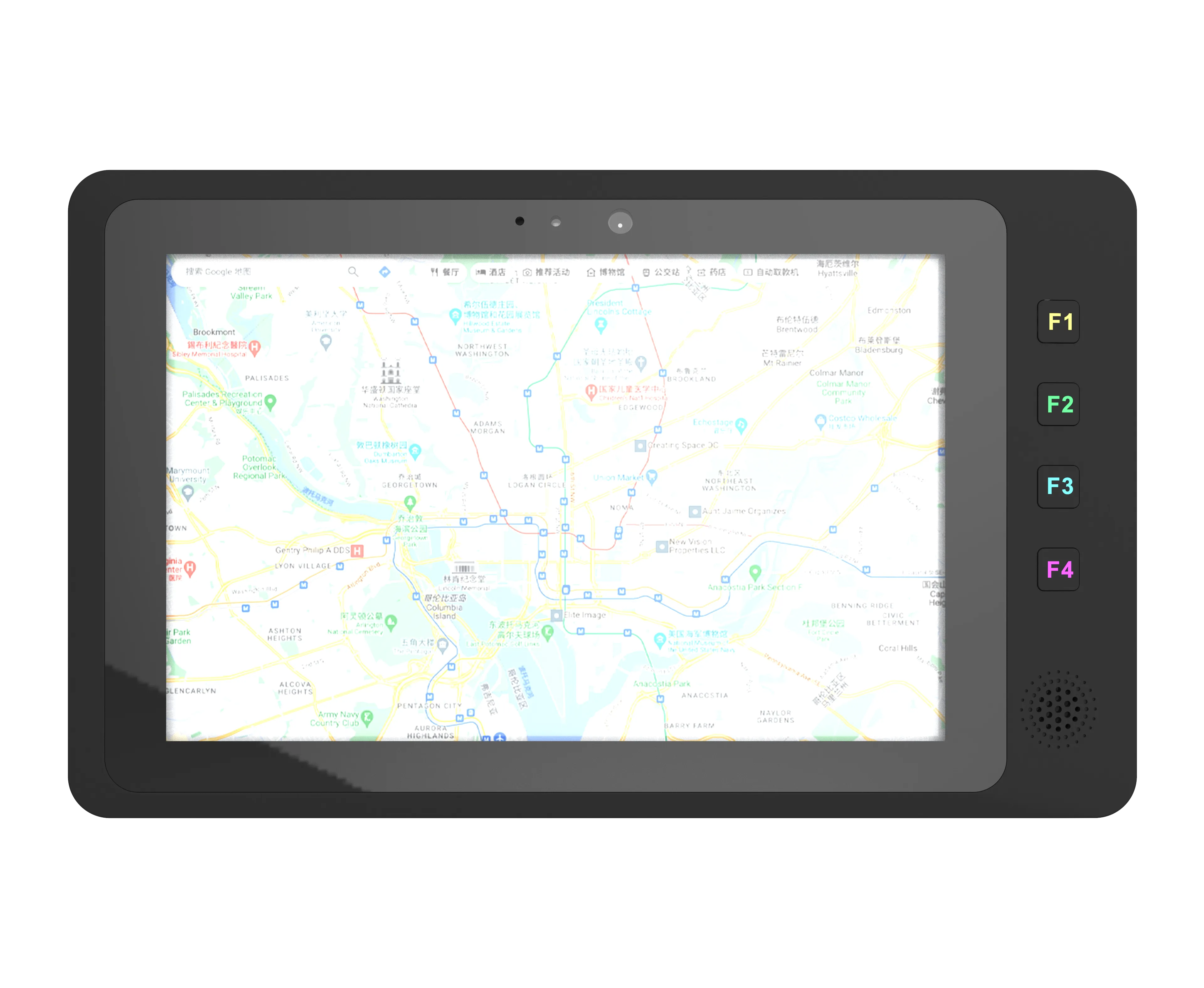
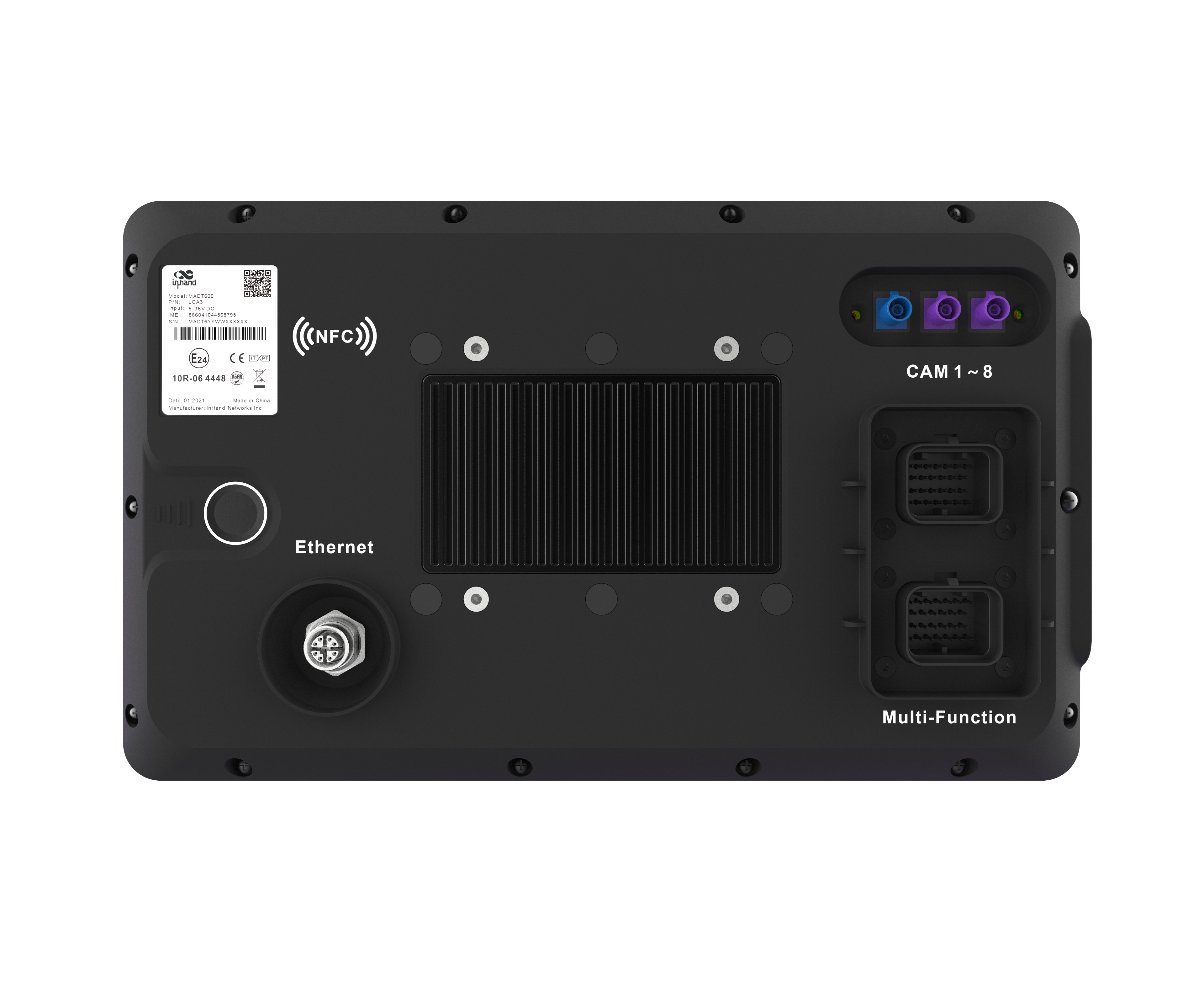
All models are equipped with blue GNSS FAKRA C-coded male connectors. Purple Celluar FAKRA D- Coded male only MDT600-XXXX-ANT external antenna model for use.
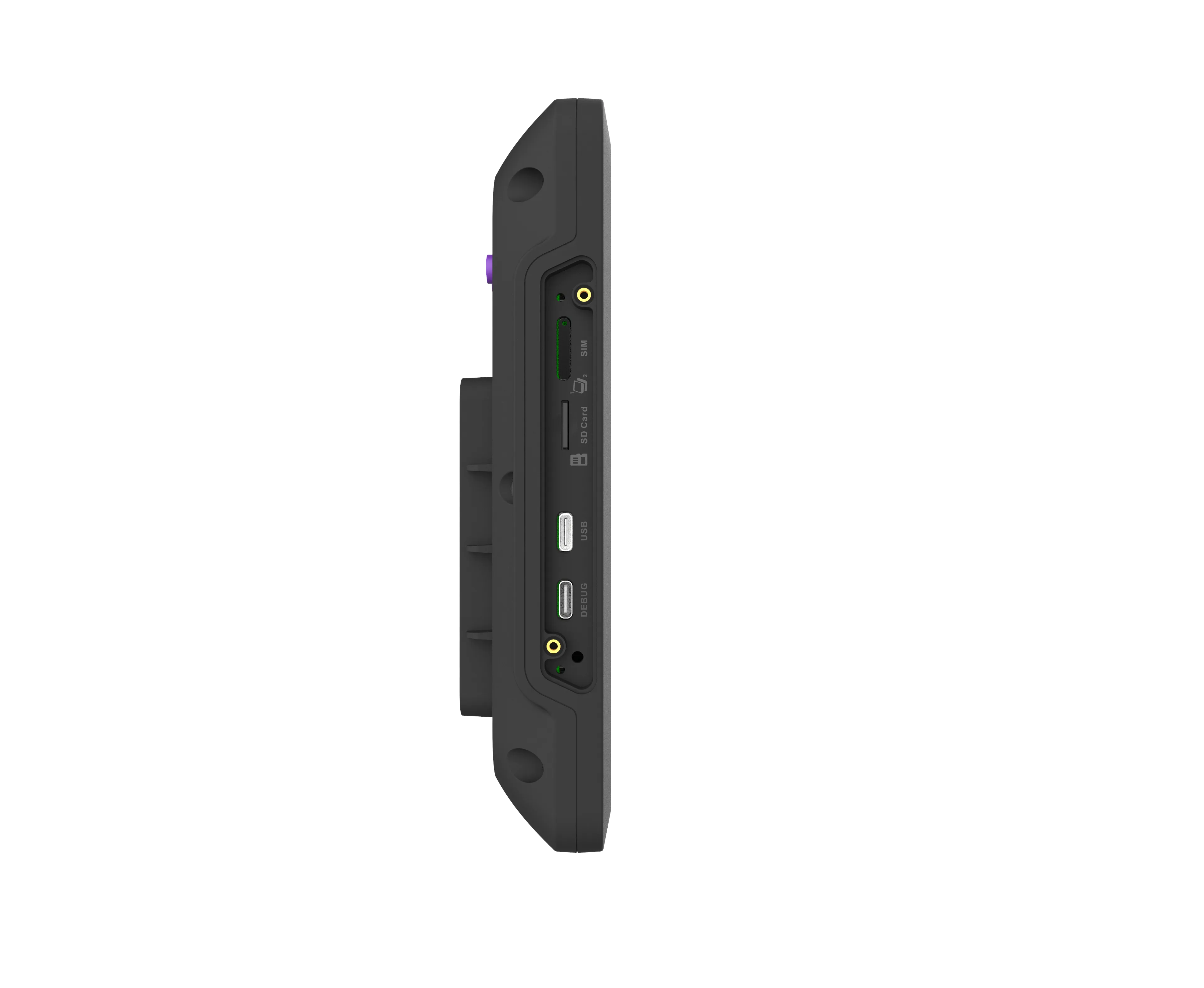
Multi-function Interface
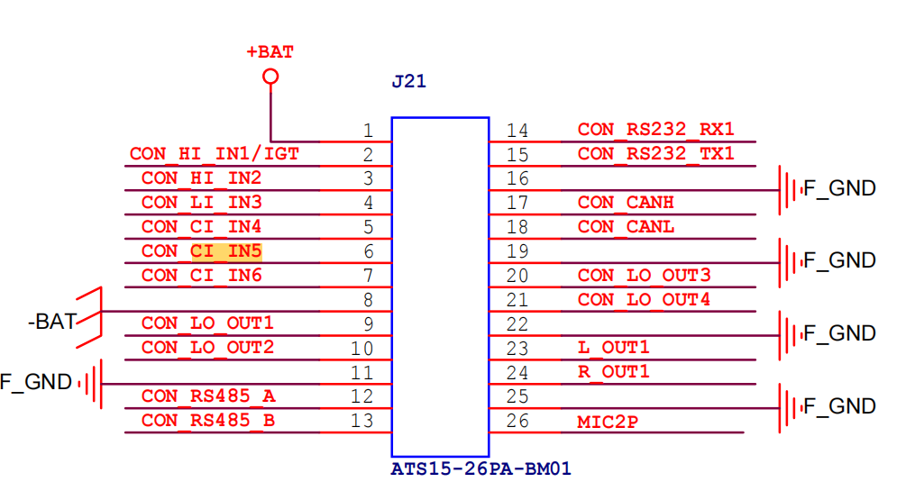
The multi-function interface is shown in the figure below:
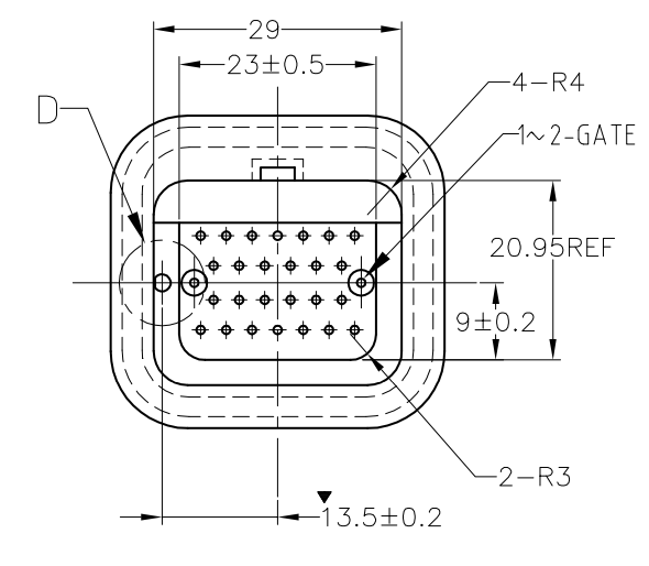
Uses Amphenol connector ECON250001 ATS15-26PA-BM01.
PIN definition, PIN numbers in order from left to right, top to bottom:
| PIN | 1 | 2 | 3 | 4 | 5 | 6 | 7 |
|---|---|---|---|---|---|---|---|
| 1 | VIN+ | IGT | HI_IN2 | LI_IN3 | CI_IN4 | CI_IN5 | CI_IN6 |
| PIN | 8 | 9 | 10 | 11 | 12 | 13 | |
| 2 | VIN- | LO_OUT1 | LO_OUT2 | GND | RS485_A | RS485_B /RS232_TX | |
| PIN | 14 | 15 | 16 | 17 | 18 | 19 | |
| 3 | RS232_RX | CAN1-H | CAN1-L | CAN-H | CAN-L | GND | |
| PIN | 20 | 21 | 22 | 23 | 24 | 25 | 26 |
| 4 | LO_OUT3 | LO_OUT4 | GND | Left Channel Audio Output | Right Channel Audio Output | GND | MIC |
- The figure above shows the pinout for version MB V1.4. For version MB V1.3, PIN13 is RS485B, and PIN15 is RS232_TX.
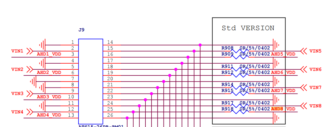
The hardware design schematic diagram is as follows:
Video Interface
| PIN | 1 | 2 | 3 | 4 | 5 | 6 | 7 |
|---|---|---|---|---|---|---|---|
| GND | VIN1 | VDD1 | GND | VIN2 | VDD2 | - | |
| PIN | 8 | 9 | 10 | 11 | 12 | 13 | |
| GND | VIN3 | VDD3 | GND | VIN4 | VDD4 | ||
| PIN | 14 | 15 | 16 | 17 | 18 | 19 | |
| GND | AHD5 | VCC5 | GND | AHD6 | VCC6 | ||
| PIN | 20 | 21 | 22 | 23 | 24 | 25 | 26 |
| GND | AHD7 | VCC7 | GND | AHD8 | VCC8 | GND |
1 | |
Development Environment Preparation
Driver Installation
Please use DriverAssitant_v5.13.zipDriverAssitant_v5.13.zip to install the necessary drivers on Windows (Win11 recommended).
Enabling USB ADB Environment
Physical Connection
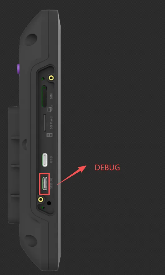
Connect one end of the Type-C cable to the PC and the other end to the debug port of the MDT600, as shown below:
Entering Developer Mode
- Click on System Settings.
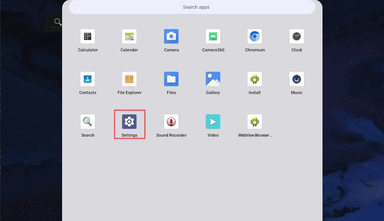
- Click "About tablet", then repeatedly tap "Build number".
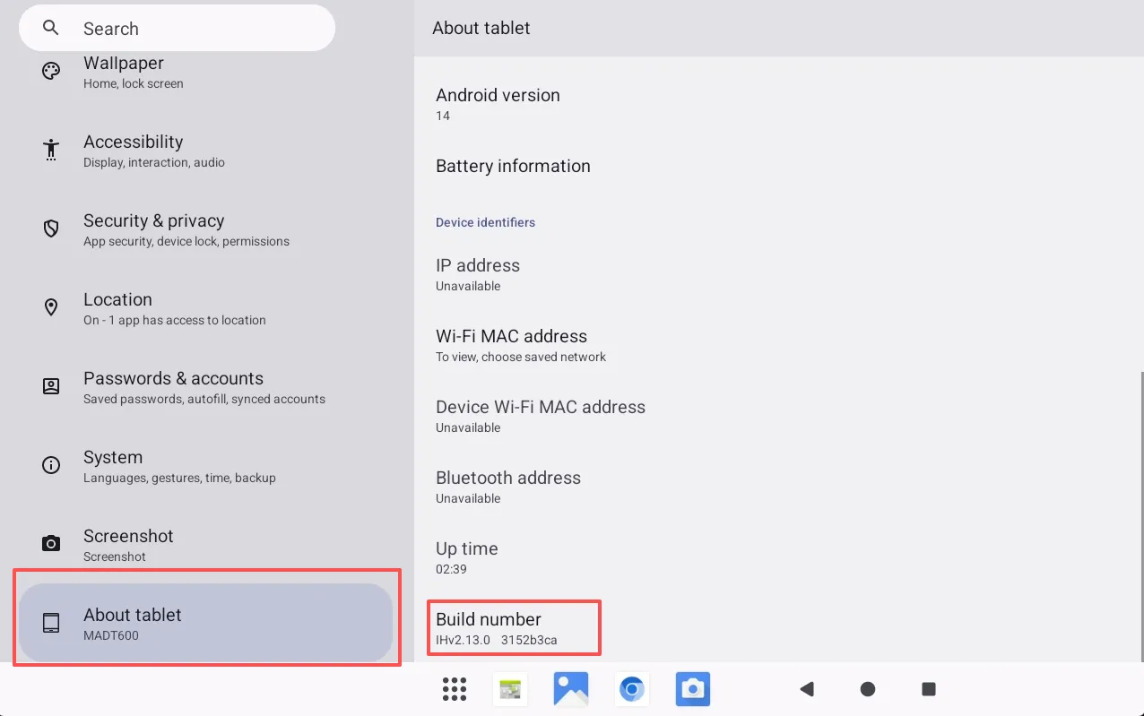
- Continue until "No need, you are already a developer" appears.

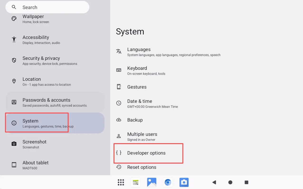
- Then click "System", find "Developer options".
Enabling USB Debugging
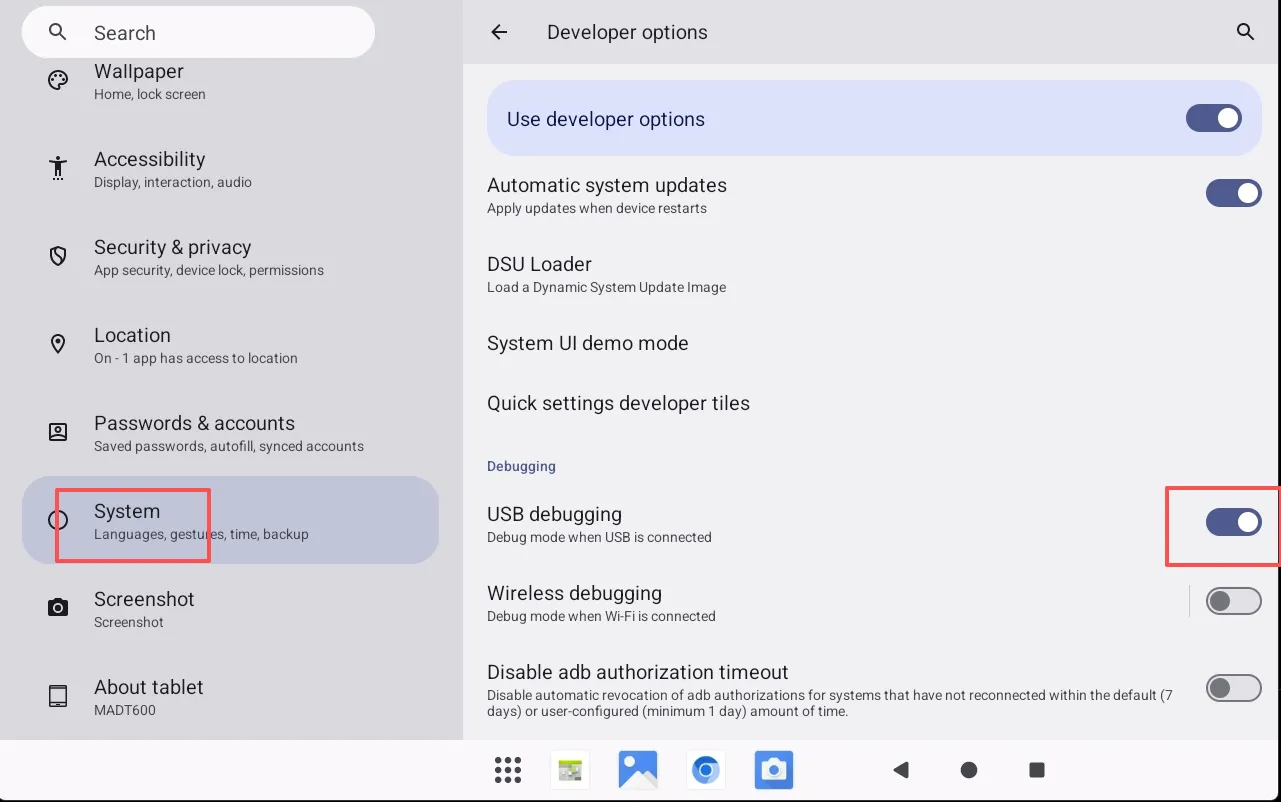
In the Debugging section, turn on "USB debugging".
Downloading ADB Software
Download the ADB software. Please refer to the following link to download Android's platform-tools:
Executing adb shell
Execute the adb shell command. If successful, it indicates the ADB environment has been set up correctly, as shown below:

For ADB usage, please refer to the following link:
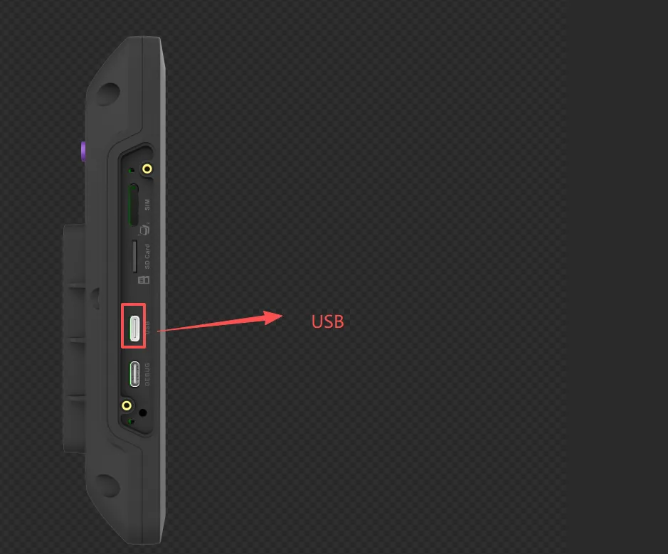
Note: ADB uses the debug port, but the debug port and the USB port are mutually exclusive because they share the same host controller. When using the debug function, the USB acts as a device. When using the USB port, e.g., for external USB drives or mice, the USB acts as a host. The following figure shows the USB port:
Enabling Network ADB
On the MDT600 device, using Network ADB is recommended over USB ADB because USB ADB may cause the cellular network and USB port to be unavailable, as the cellular modem and the USB port use the same USB host controller.
Connecting to WiFi
Connect both the MDT600 and the computer to the same local area network via WiFi.
Enabling Wireless Debugging
Enter Developer Options
Open Developer Options, please refer to section 2.2.2.
Enable "Wireless debugging"
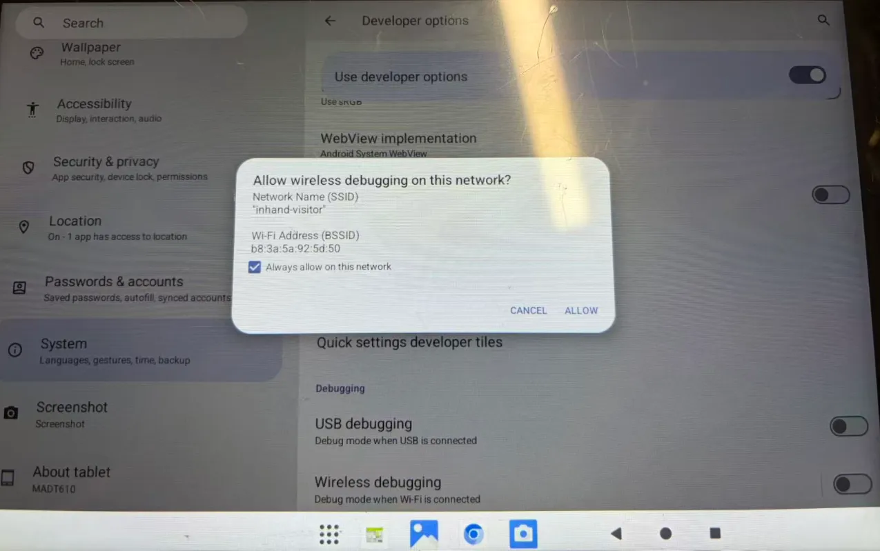
Connecting to Device via Network ADB
Obtain the device's Wireless network IP address.
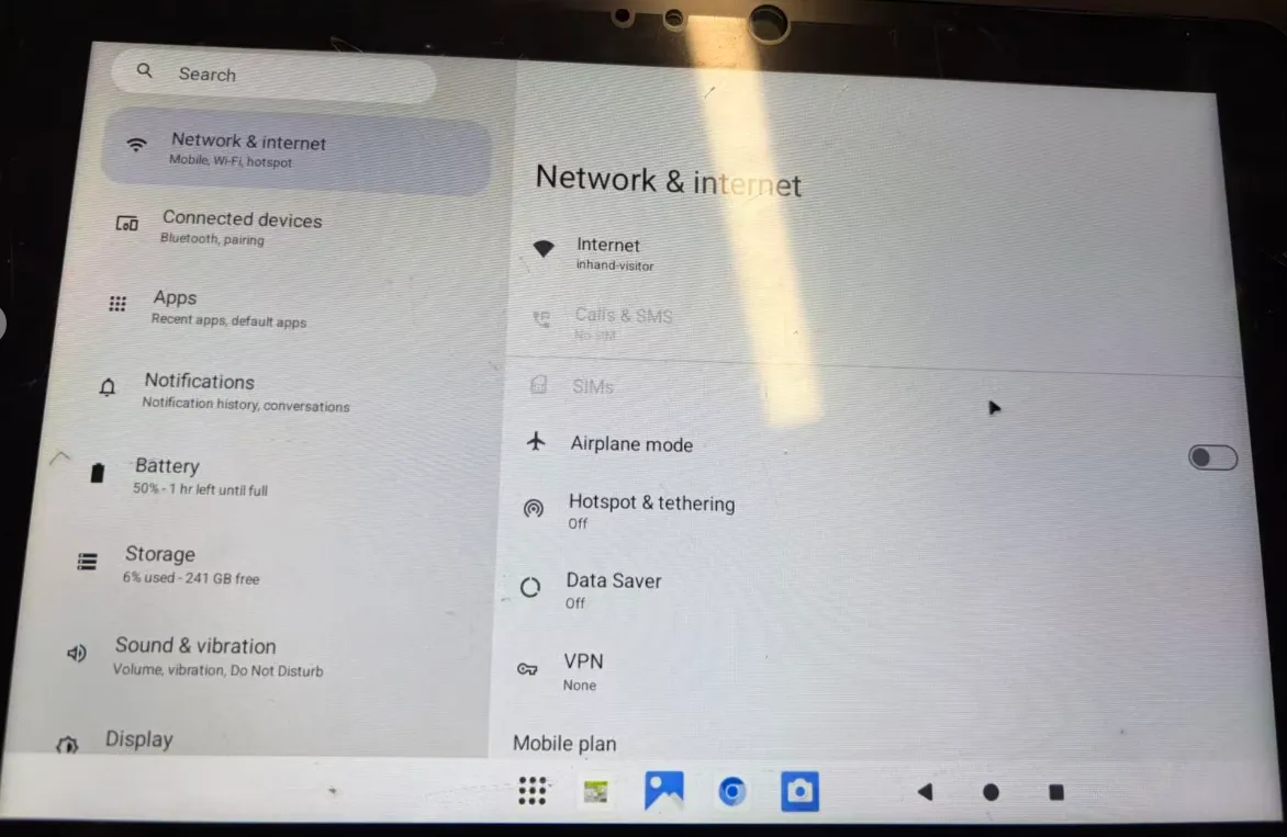
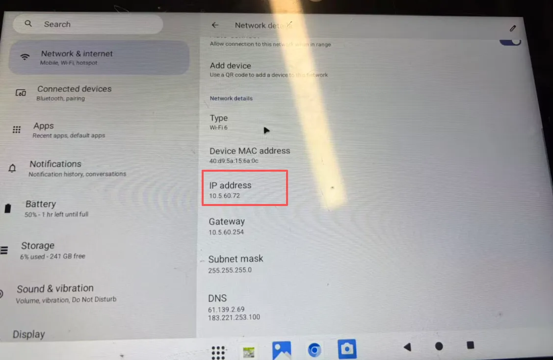
Connect to the device
Firmware Flashing and OTA Upgrade
If the device cannot boot normally, you can try to recover the device by flashing the firmware. The steps for firmware flashing are as follows.
Firmware Flashing
Extract the flashing tool
Extract the flashing tool RKDevTool_v3.30_for_window.zip.
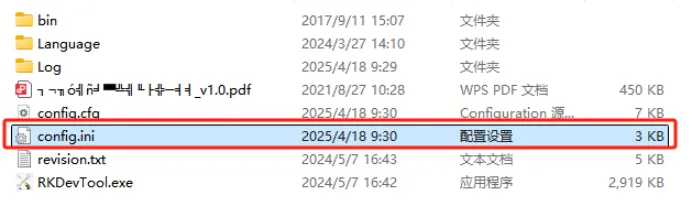
Modify Configuration
Open config.ini with a text editor and set Selected to 2 (1-Chinese, 2-English).
Browse Firmware
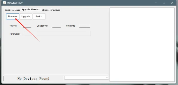
Run RKDevTool.exe, then select "Upgrade Firmware", click "Firmware" to browse to the firmware file, e.g., MADT600_std_fw_2.13.0_20251114.1752.img.
Device Entering Download Mode
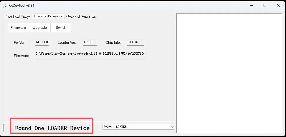
Connect one end of the Type-C cable to the PC and the other end to the MDT600's debug port. Press and hold the F3 button while powering on the device. The device will enter recovery mode. Then execute the command adb shell reboot loader. After the device restarts, RKDevTool will discover a loader device, as shown below:
Flashing
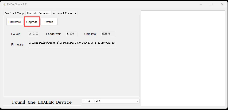
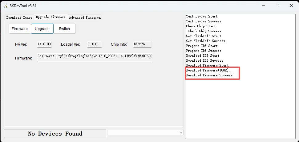
Click "Upgrade" and wait until the flashing is complete.
OTA Upgrade
USB Drive Upgrade
Copy OTA package to USB drive
Copy the OTA upgrade package, e.g., MADT600-ota-2.13.0-20251114.1752.zip, to the root directory of the USB drive and rename it to update.zip.
Disable USB Debug on the device
Turn off USB Debug mode in Developer Options. Disconnect the PC from the debug port because the debug port and USB port are mutually exclusive.
Upgrade
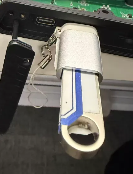
Insert the USB drive into the MDT600, as shown below:
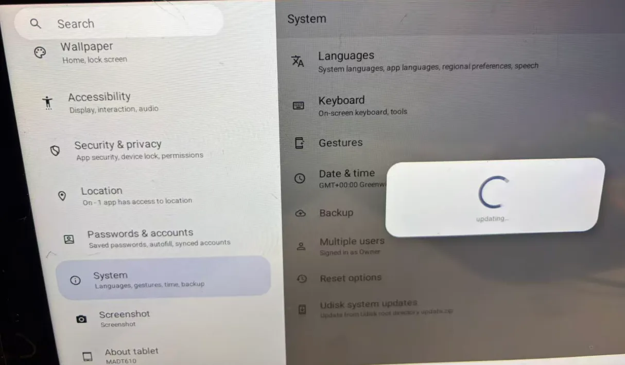
Then click "Settings" -> "System" -> "Udisk system updates", as shown below:
Command Line Upgrade
Push OTA package to the device
Push the OTA upgrade package to the device and rename it to update.zip.
Execute the upgrade command
Execute the upgrade instruction:
Android Peripheral Interface Development Guide
Ethernet
Ethernet can be configured as a WAN interface or a LAN interface. As a LAN interface, only the IP address and subnet mask need to be configured for this network interface. If configured as a WAN port, the IP address, subnet mask, gateway address, DNS address, etc., need to be configured.
WAN Interface
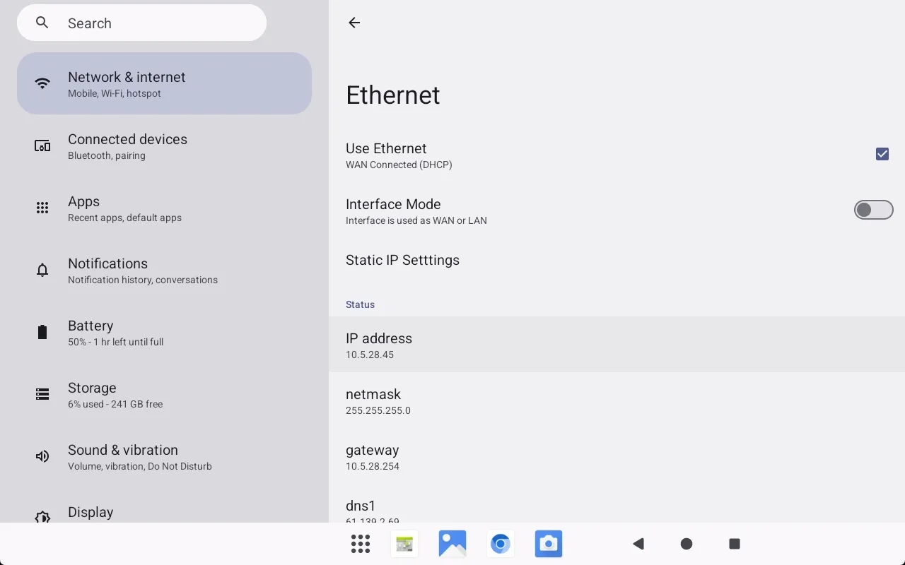
When used as a WAN interface, it can obtain an IP address via DHCP or use a static IP configuration.
DHCP
The figure below shows the DHCP networking method.
STATIC IP
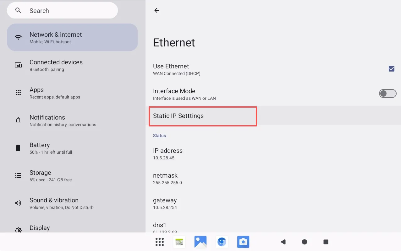
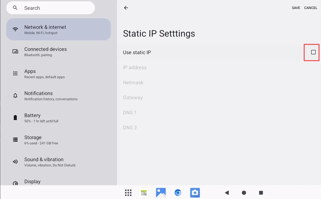
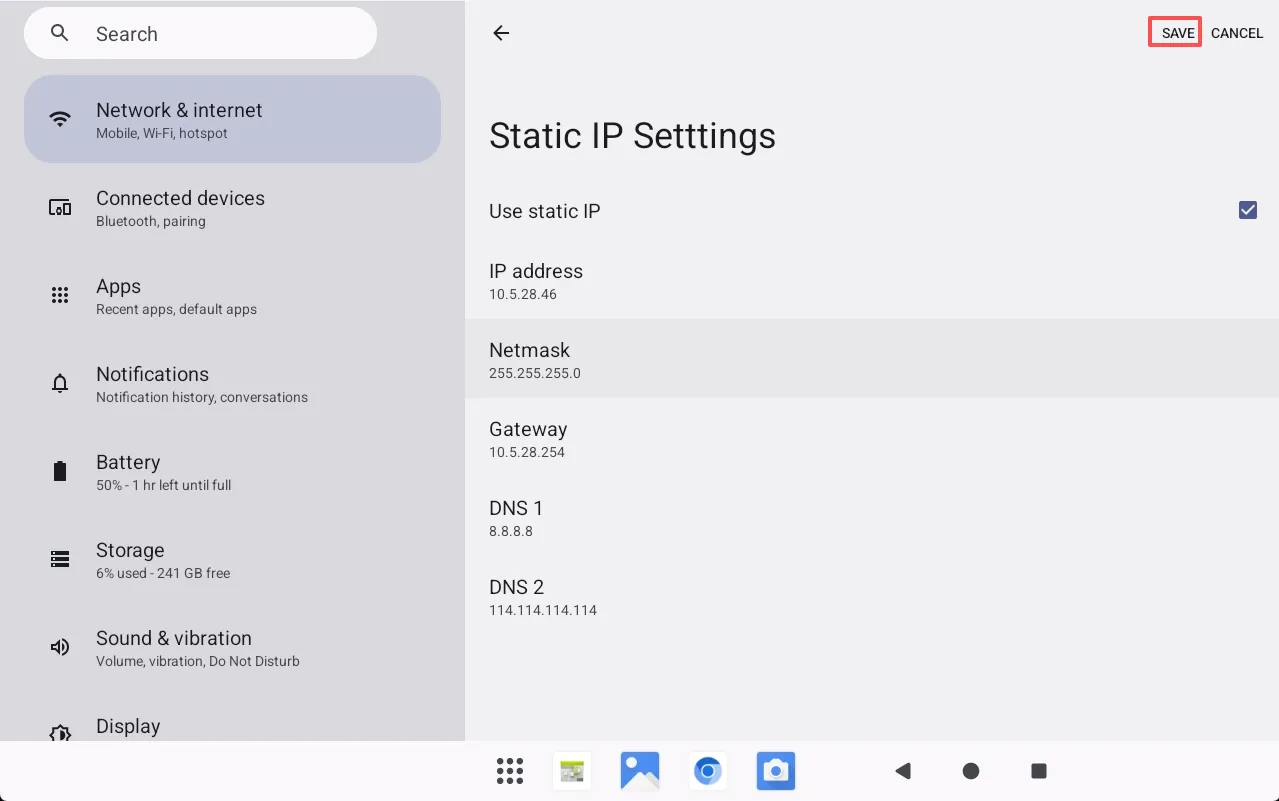
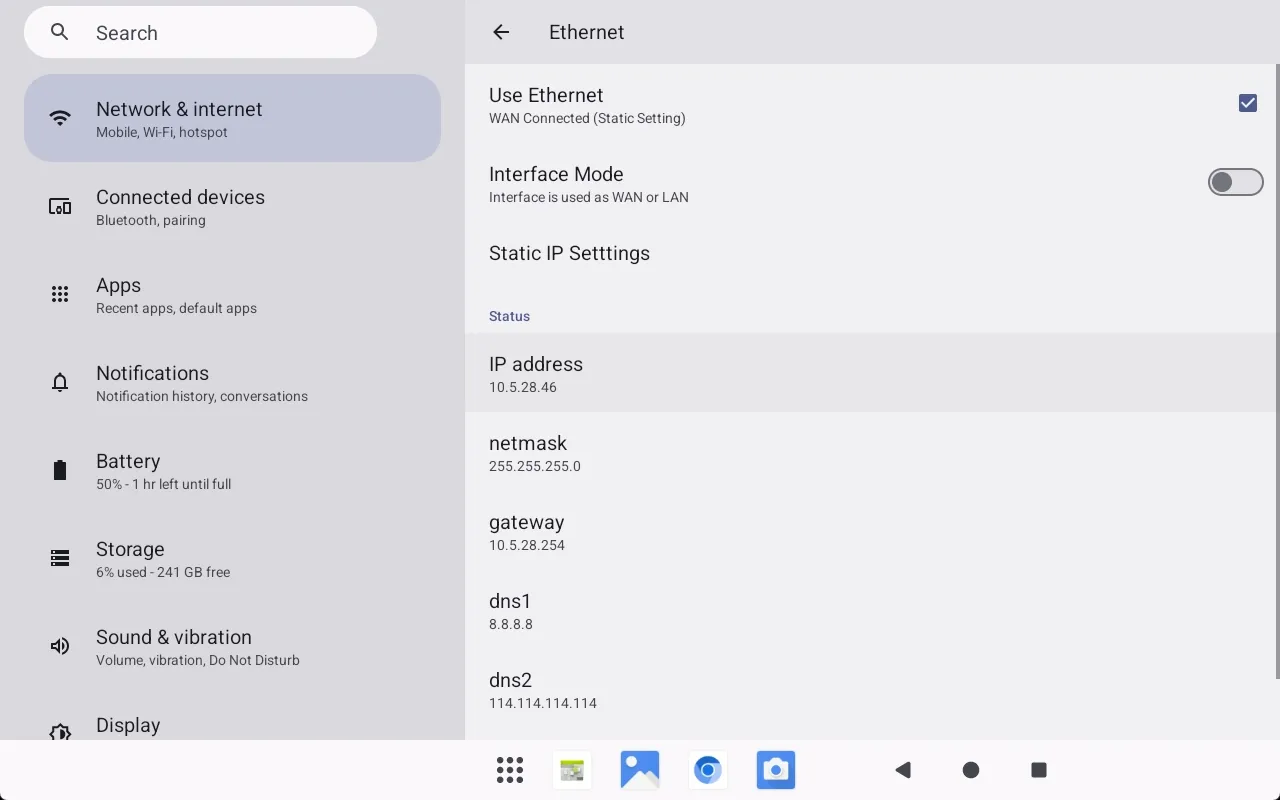
The figure below shows the operation method for setting a static IP.
First, click on Static IP Settings.
Check the box to use a static IP.
Fill in the IP address, Netmask, Gateway, DNS1, DNS2 respectively. Then click SAVE.
LAN
Switch between WAN or LAN mode by clicking the interface mode, as shown below:
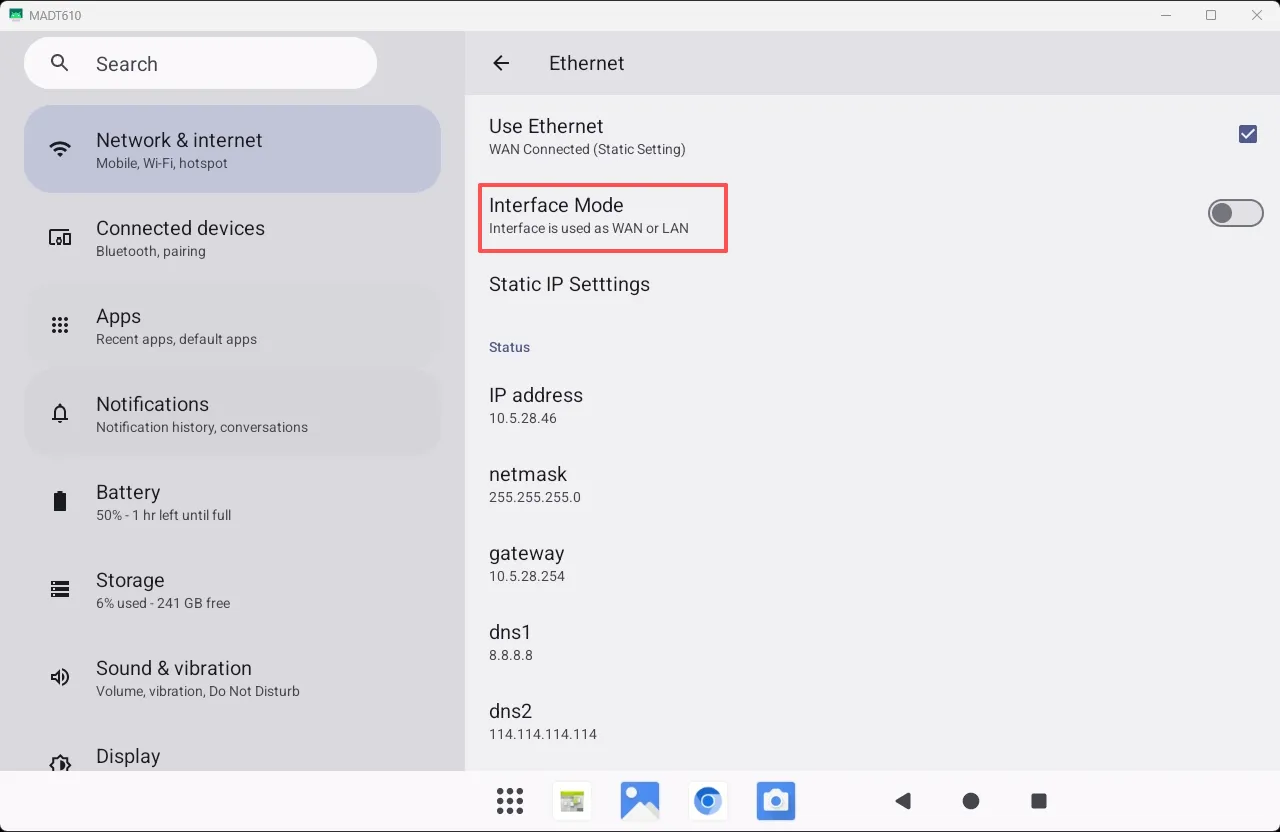
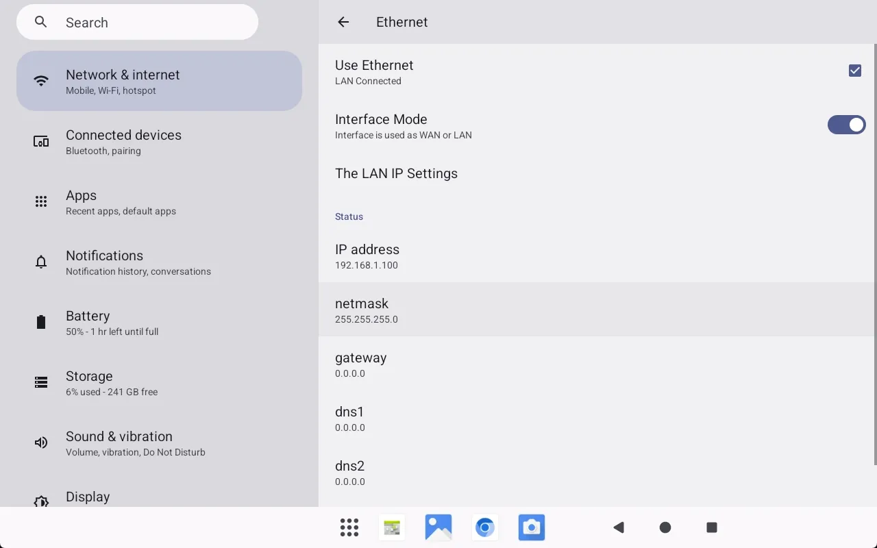
After switching to LAN mode, the default IP address and subnet mask are 192.168.1.100 and 255.255.255.0, respectively.
Audio
Audio Playback
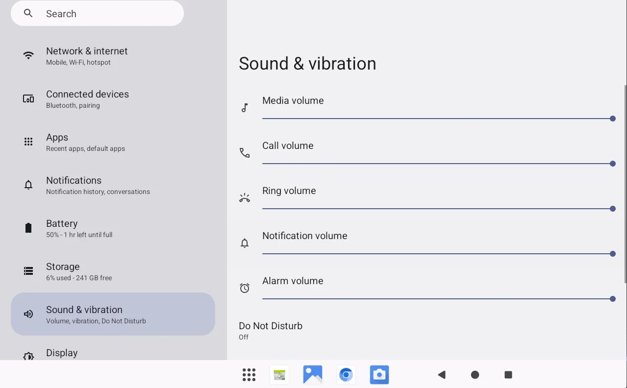
The MDT600 has a built-in SPEAKER and also supports analog audio output on PIN-23 and PIN-24 of the Multi-Function interface.
For volume adjustment, please refer to the following image:
Audio Recording
Description
The MDT600 has a built-in MIC and also supports analog audio signal input (Headset), connected via PIN26 of the Multi-Function interface.
Demo Project
app_test_audio.zip
The demo project includes source code and an APK. The APK can be installed directly via the adb install command.
The testing steps for the demo project are as follows:
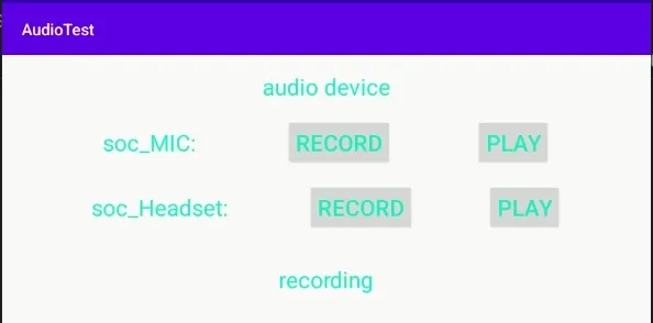
When clicking MIC Record, speak towards the MIC. The recording will last for 10 seconds and then stop automatically, displaying the save path. Then click Play to play the recorded sound. Clicking Headset works similarly.
Camera
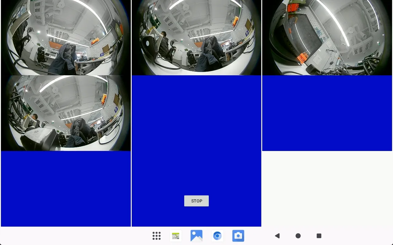
The MDT600 supports connecting up to 4 AHD cameras simultaneously. The system camera only displays the feed from the first camera. We have implemented an app that can preview multiple Camera feeds simultaneously.
app_test_locamera.zip contains the APK and source code.
First, install the APK file.
Click START to begin preview, as shown below:
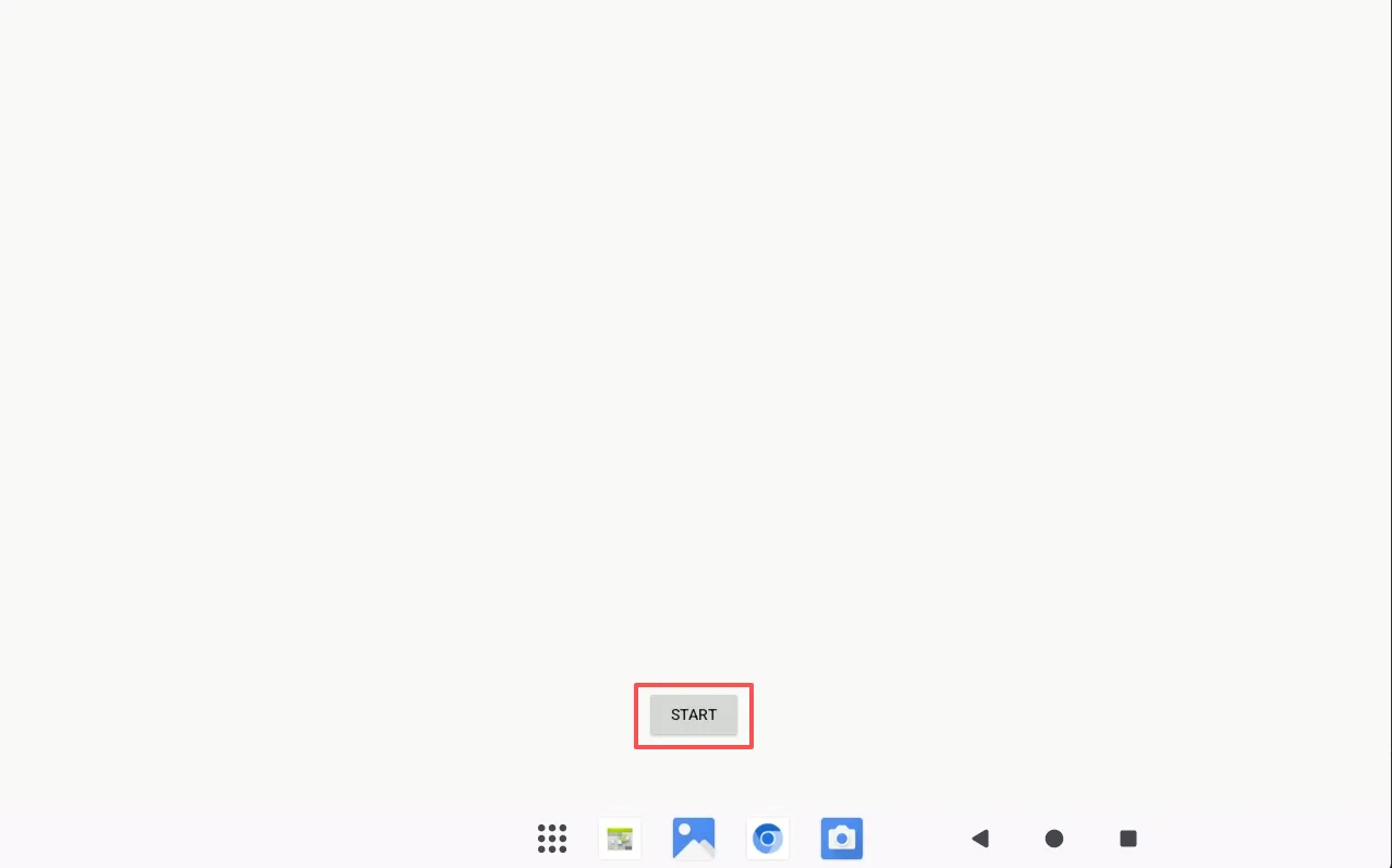
After starting the preview, the effect is as follows:
CAN
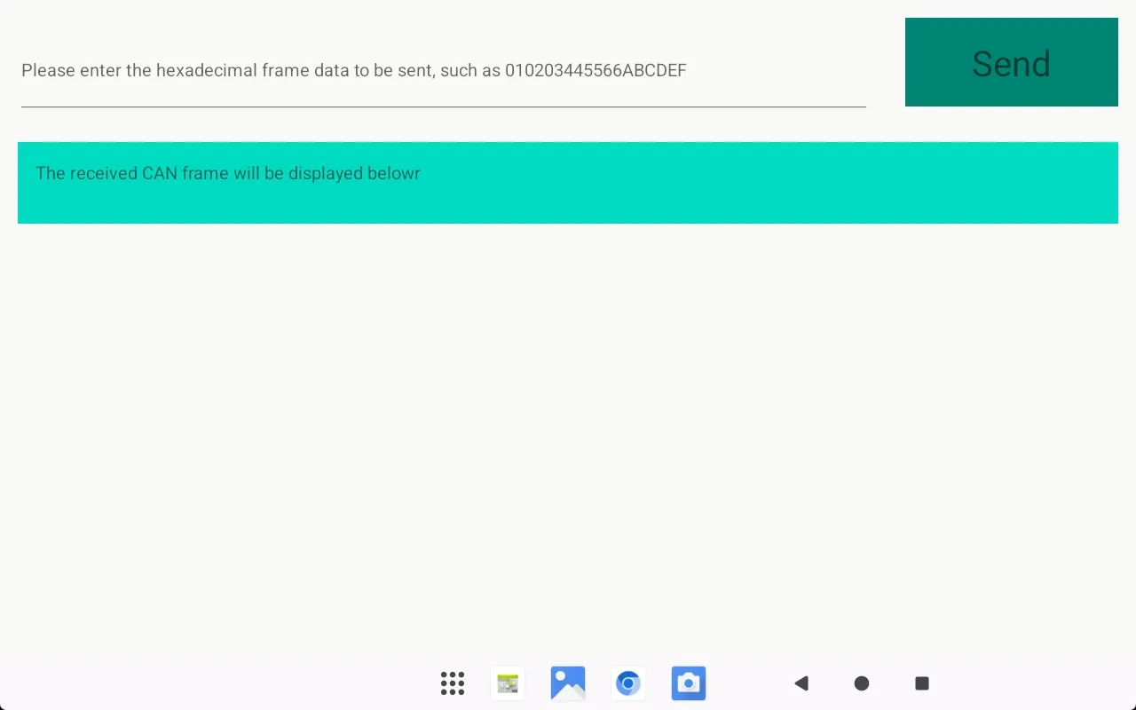
app_test_can.zip contains the test APK and source code.
The test APK is located in the apk directory as IhCANDemo_debug.apk. Install it directly via the adb command.
Note: The internal CAN bus parameter settings in IhCANDemo_debug.apk are as follows:
Open the app. The app can receive data sent by the other party and can also input data to be sent, then click "Send" to transmit.
As shown below:
NFC
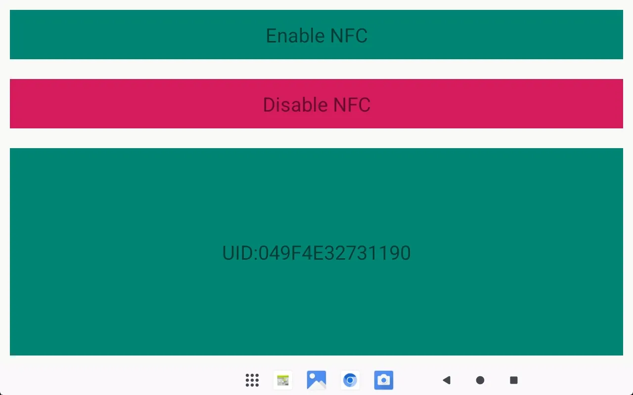
app_test_nfc.zip contains the APK and source code.
The APK is located in the apk directory within app_test_nfc.zip. The APK installation command is as follows:
After opening the APK, click "Enable NFC", then tap an NFC card on the NFC area on the back of the MDT600 to get the card ID. As shown below:
RS232/RS485
The corresponding serial port device for RS232 is /dev/ttyS8.
The corresponding serial port device for RS485 is /dev/ttyS1.
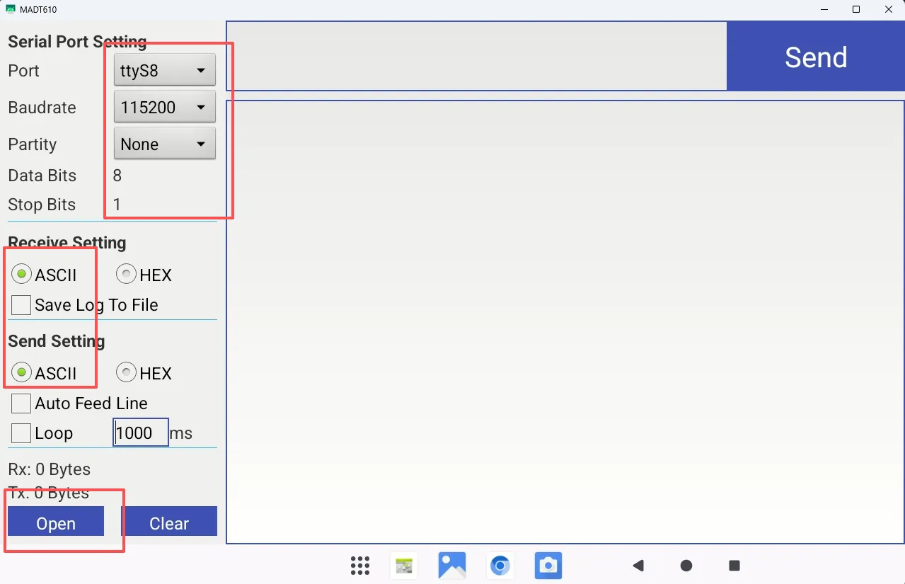
Using RS232 as an example, extract SerialPortUtility_r2.1.1.zip, then install the serial port tool via the adb command. The command is as follows:
Connect the RS232 and the peer device properly. Here, we use a USB-to-RS232 adapter connected to a PC. Then open the SerialPortUtility App. As shown below:
Input the data to be sent, for example: "MDT600 Send RS232 Test Data". As shown below:
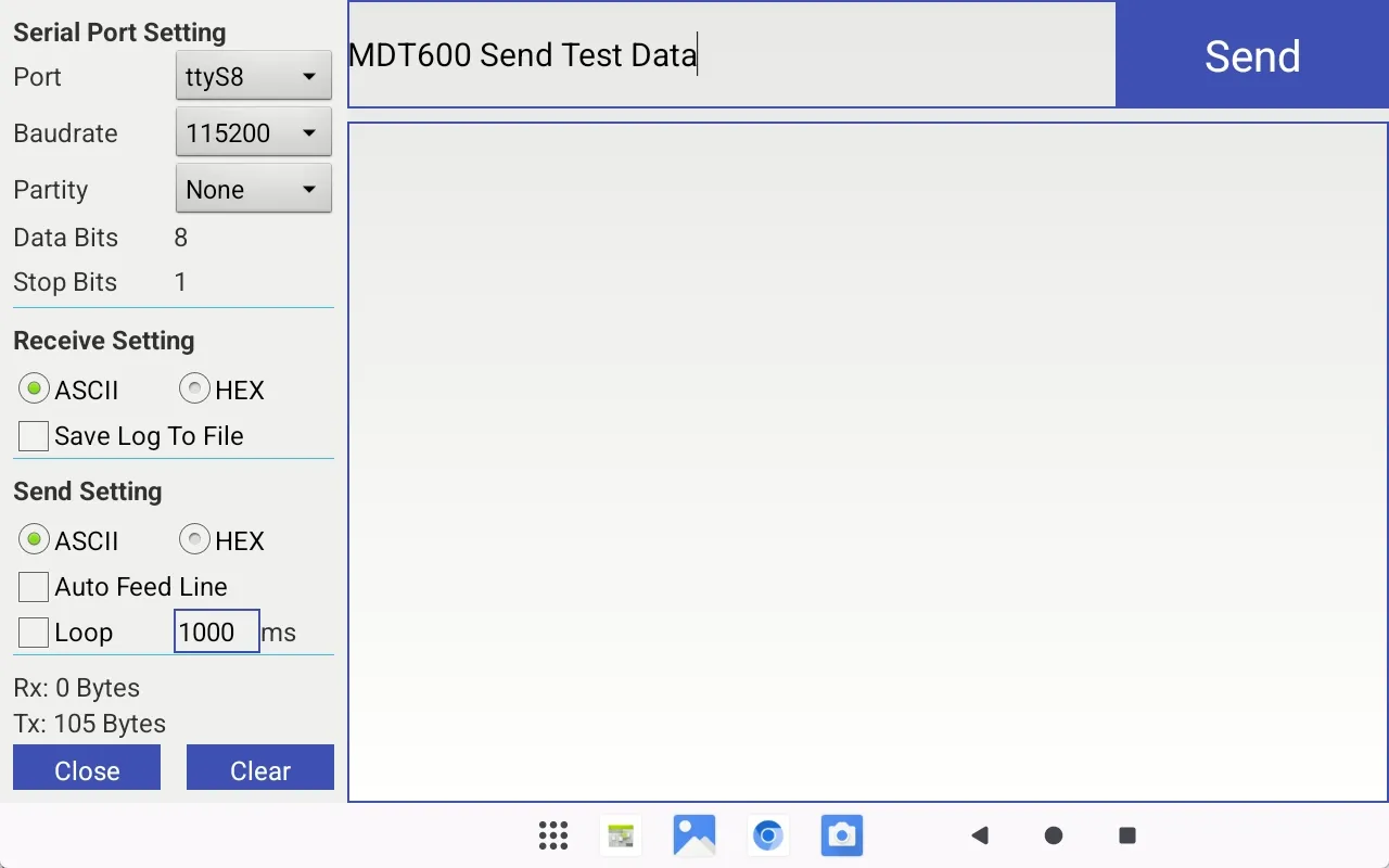
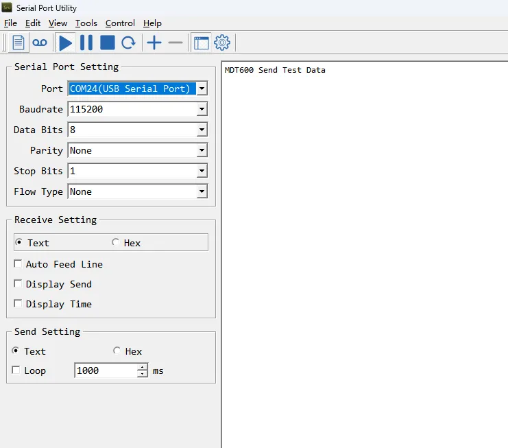
The PC end receives the data, as shown below:
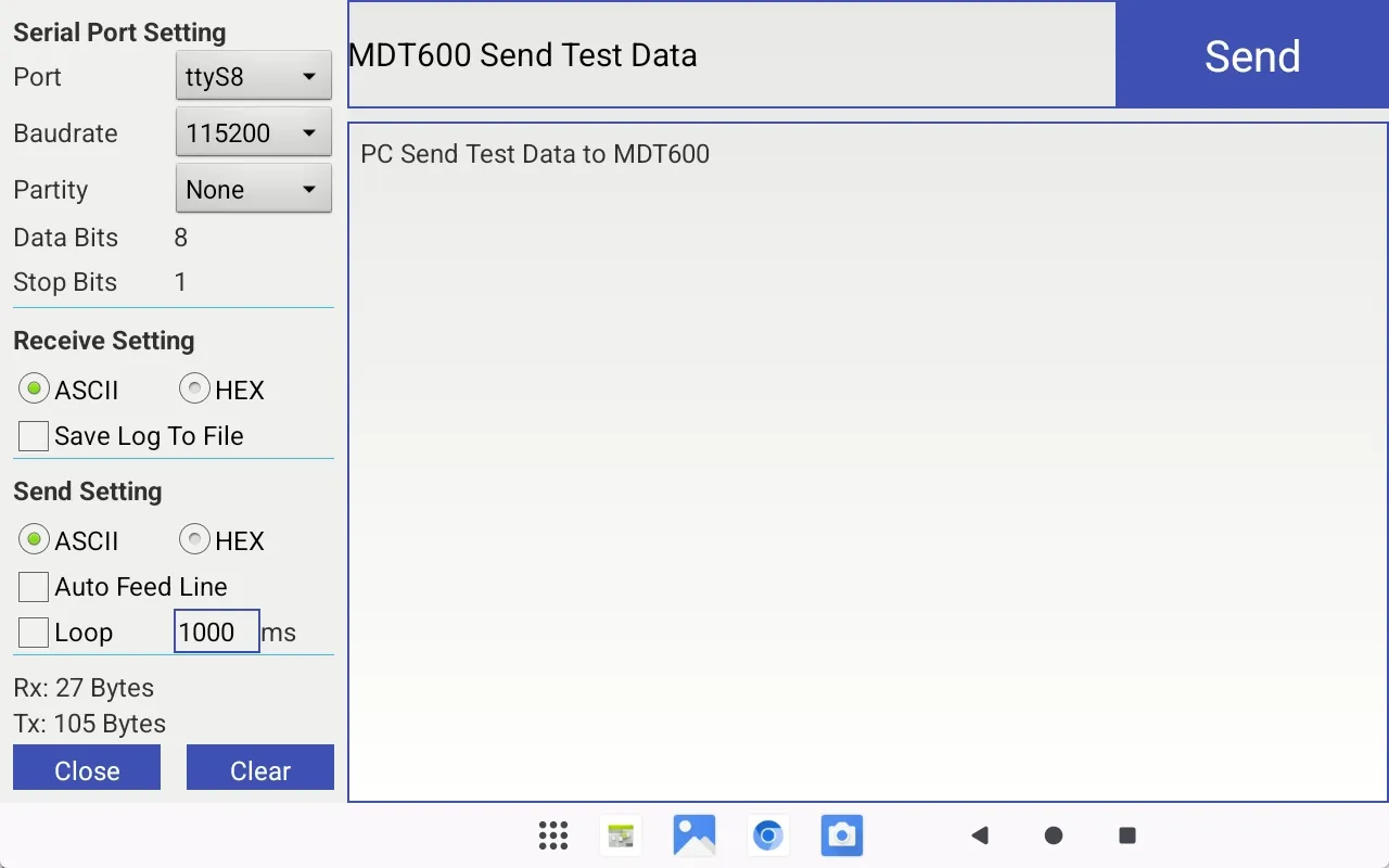
Similarly, when the PC sends data to the MDT600, as shown below:

The MDT600 receives the data, as shown below:
The testing method for RS485 is the same as for RS232.
Display
Setting System Full Screen
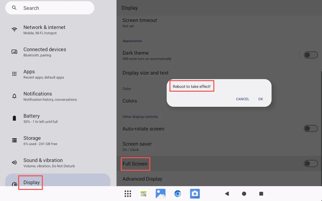
To set the system to full screen, you need to enable "Settings" -> "Display" -> "Full Screen". Note that enabling or disabling full-screen display requires a restart to take effect. As shown below:
GNSS
The version number of the GNSS module can be viewed via ADB commands, as shown below:
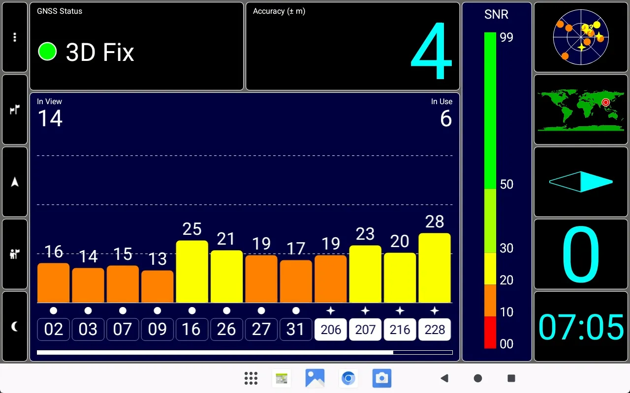
After extracting gps_test.zip, you get gps_test.apk. Then install it via the adb command.
Fingerprint
The fingerprint module includes fingerprint enrollment and fingerprint verification.
The app_test_finger.zip contains the APK and source code. Install app_test_finger-release.apk.
Fingerprint Enrollment
Click ENROLL in the APP to perform fingerprint enrollment, as shown below:
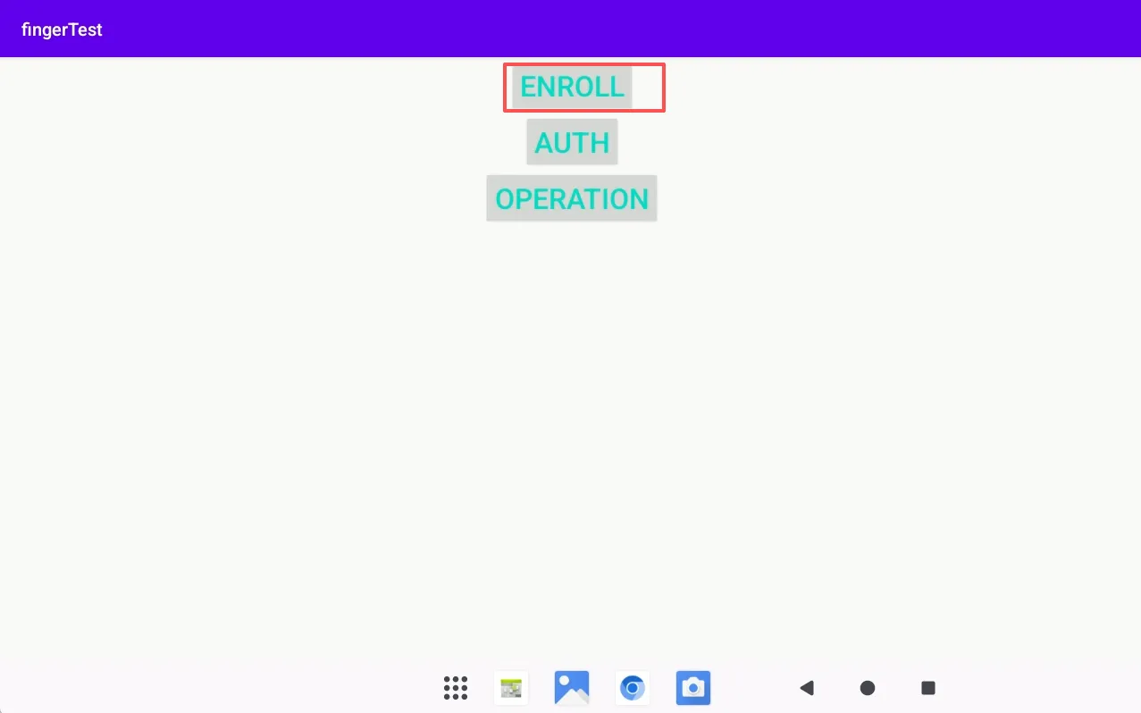
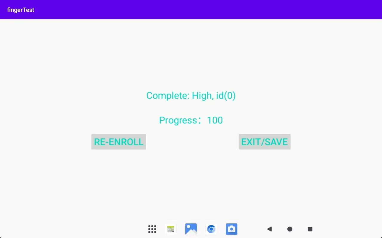
Place your finger on the fingerprint module. The enrollment progress will be displayed. If enrollment is successful, it will show 100%.
Fingerprint Verification
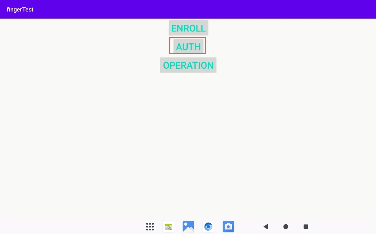
Click AUTH to verify the enrolled fingerprint. Then touch the fingerprint module. If verification is successful, it will display as follows:
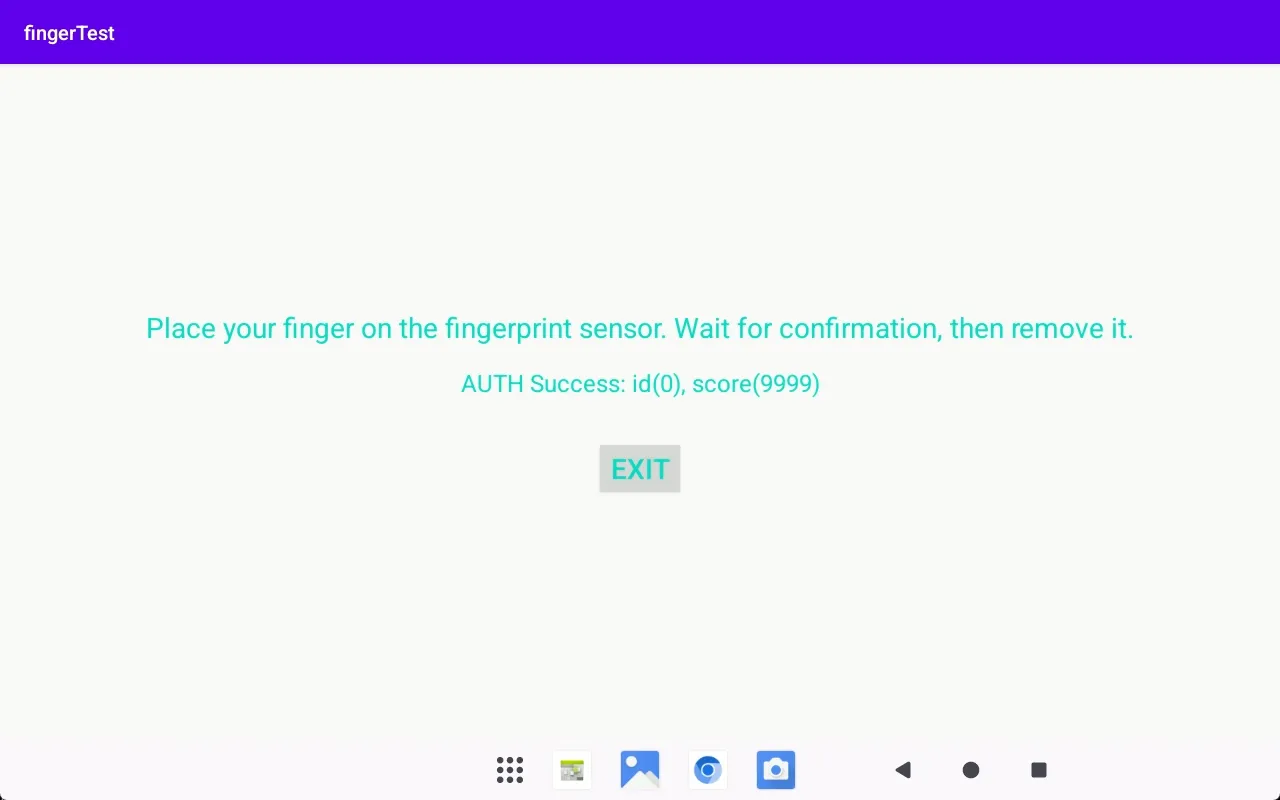
SATA
Partitioning and Formatting (Optional Operation)
Partitioning and formatting operations are mainly for replacing a new SATA disk or wanting to re-partition and format the SATA disk. Otherwise, proceed with caution to avoid data loss.
Confirm Device File
Confirm the SATA device file with the following operation:
Confirm via the command that the SATA device is /dev/block/sde.
Partition the SATA disk
The disk partitioning operation is as follows:
Format the SATA disk
ext4 filesystem
If the system has already mounted it, you need to perform an umount operation, as follows:
Perform the formatting operation:
Then restart the device. sde1 will be mounted under the /mnt/media_rw/disk directory. However, the ext4 filesystem cannot specify uid and gid when mounting, so to ensure the app can access it normally, you need to modify the permissions.
exfat filesystem
Similarly, perform the umount operation first.
Perform the formatting operation:
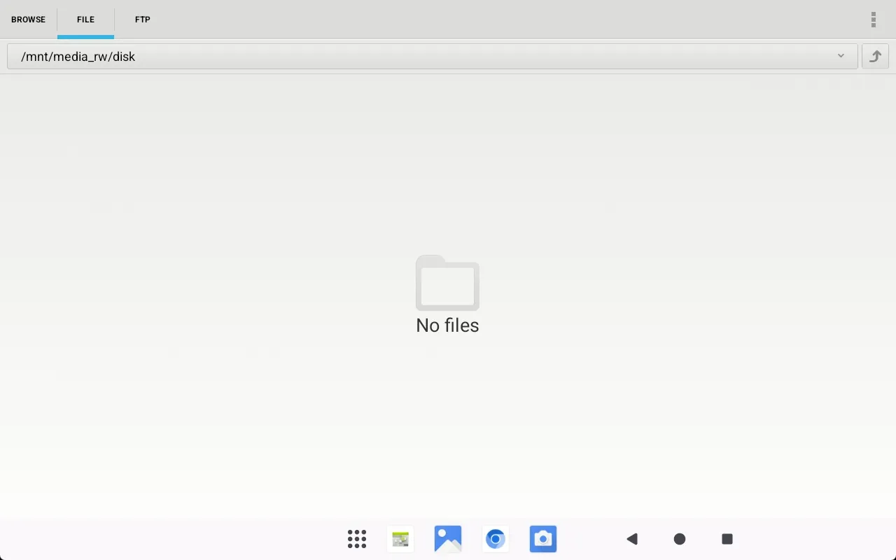
Mount Location and Read/Write
The SATA hard drive is mounted at /mnt/media_rw/disk. You can read and write to this directory through a file manager.
IMU
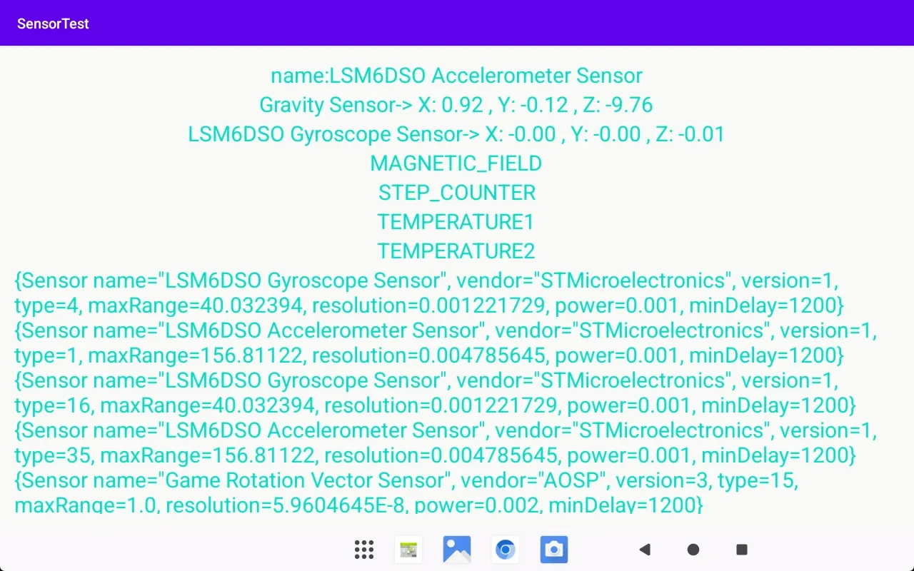
The IMU module uses the LSM6DSOW module, which integrates a 3-axis digital accelerometer and a 3-axis digital gyroscope.
app_test_sensor.zip contains the APK and source code. After extraction, the APK file can be found in the apk/release directory. Then install it via adb.
Then open the app, and you will get the following display:
EEPROM
Device Node
The read/write device node for the EEPROM is located at /sys/bus/nvmem/devices/5-00501/nvmem.
Read Operation
Write Operation
Buttons
F3
The F3 button is mapped to the key value KEY_F12.
Simultaneously, the Android framework layer will map this key value to a broadcast:
F4
The F4 button is mapped to the key value KEY_POWER.
MCU
The MCU can control the background lights of buttons F1 and F2, read F1 and F2 button events, and also read DI (Digital Input) and output DO (Digital Output).
The Android firmware comes with a built-in mcu command tool to read/write MCU registers to get/control the corresponding peripheral information.
serial-mcu-master.zip contains the source code for the mcu command. It can be integrated into your own programs.
MCU Register Information: MADT MCU Registers
MCU Register Protocol: MDT MCU Protocol
Register Read/Write
Before writing to a register, you need to execute the unlock write protection, otherwise writing to the register will fail.
MCU firmware version number

Read the firmware version number:
The firmware version number can be seen from the returned result as 0x03.
Button Reading
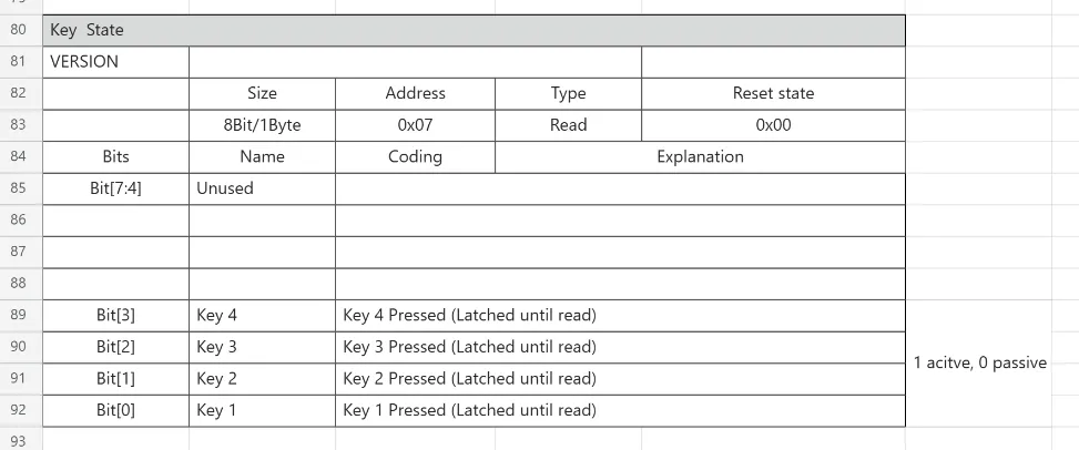
| Name | Description |
|---|---|
| Key1(F1) | When a key is pressed, the corresponding bit is set to 1. After a successful read, the next read will set it to 0. |
| Key2(F2) |
In the current device, only Key1 (F1) and Key2 (F2) events can be read.
The following shows reading an F1 button event.
The following shows reading an F2 button event.
LED Control
LED Color
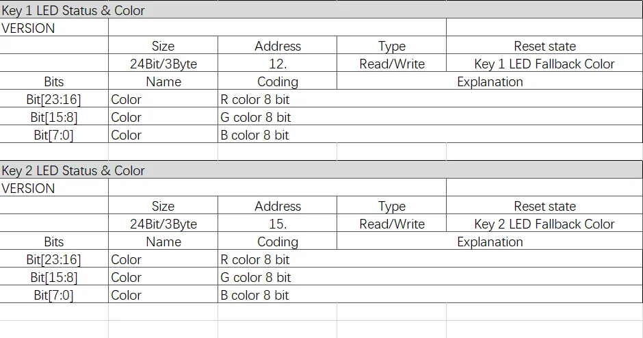
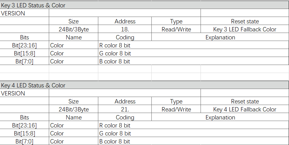
Key[1-4] Led Status & Color is used to view and set the button color (BGR format).
The following shows viewing the Key1 (F1) button's background light.
The read value is FF(B) FF(G) FF(R), indicating white.
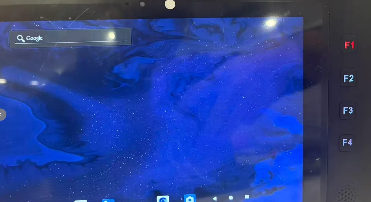
Below we set the Key1 (F1) button's background light to red.
The display effect is as follows:
LED Status
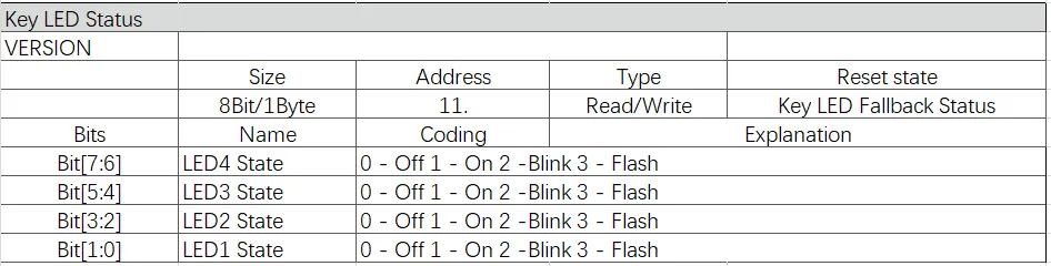
The following shows viewing the status of the four LEDs.
The following sets the four LEDs to blink.
LED Brightness
The brightness of the LEDs of the 4 groups of keys is uniformly controlled by a register.

Query brightness:
Set the brightness and set it to the maximum value:
Input/Output
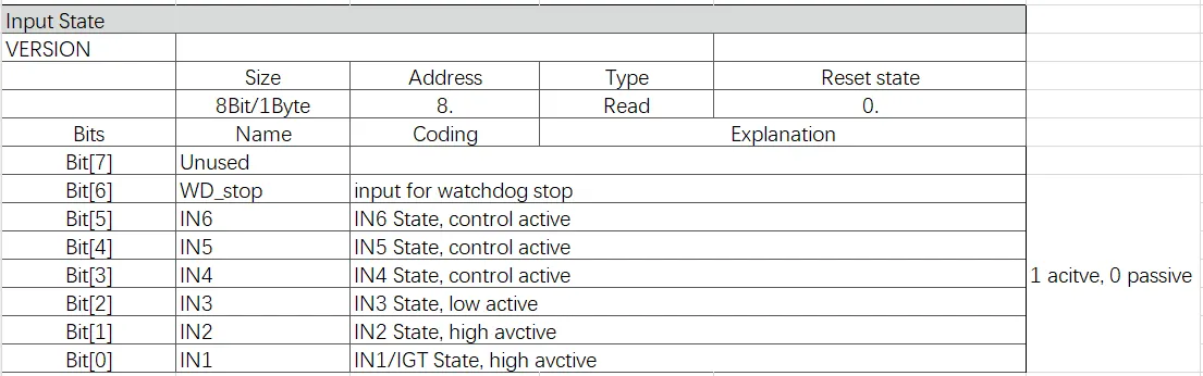
Input
| Name | Description |
|---|---|
| IN1-IN6 | DI Input |
| WD_stop | The CPU will periodically (15s) toggle a GPIO connected to the MCU. If the MCU does not detect the GPIO toggling continuously for 3 minutes, it will reset the CPU. Here, WD_stop instructs the MCU not to perform this check. This function is mainly used during firmware flashing when the CPU cannot perform the signal toggling (feed the dog) operation, thus avoiding a reset. |
The following shows reading the DI register information:
The returned value is 41, indicating that the ignition signal IN1/IGT was read, and WD_stop was also read.
Output
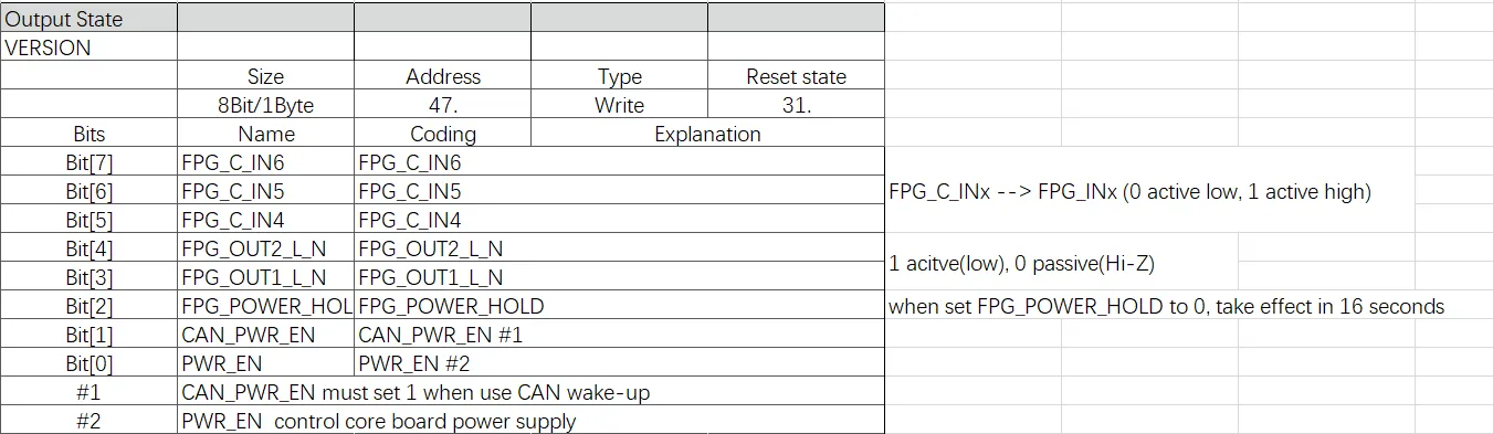
Input Active Level Control
| Name | Description |
|---|---|
| FPG_C_IN4 | Controls the active level of the DI input. If 0, it means active low; if 1, it means active high. |
| FPG_C_IN5 | |
| FPG_C_IN4 |
Output
| Name | Description |
|---|---|
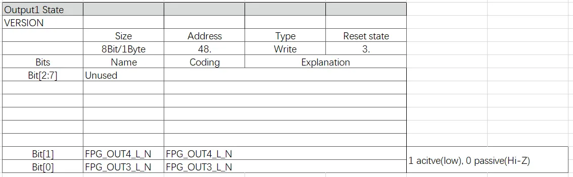
| FPG_OUT1_L_N | DO output. If the value is 1, it outputs low; otherwise, it outputs high impedance. |
| FPG_OUT2_L_N | |
| FPG_OUT3_L_N | |
| FPG_OUT4_L_N | |
| FPG_POWER_HOLD | When the IGT signal value is 0, whether to continue supplying power to the CPU. If this value is 0, power will be cut off immediately; if this value is 1, it will continue to supply power to the CPU. |
| CAN_PWR_EN | After cutting power to the CPU, whether to supply power to the CAN module. If this value is 1, it means power will be supplied to the CAN module. When the CAN module receives a wake-up signal frame, it will send an interrupt to the MCU, and the MCU will then supply power to the CPU. |
| PWR_EN | Controls whether to supply power to the CPU. This value should be 1. |
The following shows a register read operation.
Register 2f returns a value of 1F, indicating that FPG_OUT1_L_N and FPG_OUT2_L_N are outputting low; CAN_PWR_EN is 1; PWR_EN is 1; FPG_POWER_HOLD is 1.
The following sets IN4-IN6 to active high input.
Temperature

Read the temperature:
"(MCU)# 02 A2 01 09 25 8F 03, where 25 indicates a temperature of 25 degrees Celsius."
Other
Startup script
After the system starts up, it will check if the file /sdcard/setup.shexists. If it exists, the system will execute this script.
Prepare the script and use the following command to place the file at /sdcard/setup.sh:
Then, check and test if the setup.shscript has any issues:
If there are no errors, it indicates that the script executed successfully. You can use the following command to view the execution logs of the script.
1 | |
1 | |
1 | |
Note:Please note that only versions after February 5, 2026, support automatically executing <font style="color:#DF2A3F;">/sdcard/setup.sh</font>.