Declarations
Copyright © InHand Networks. All rights reserved. No part of this document may be reproduced, transmitted, or distributed in any form or by any means without prior written consent from InHand Networks.
Disclaimer The contents of this document are subject to change without notice due to product updates or other reasons. InHand Networks reserves the right to modify the document contents without any notice or prompt. This manual is intended only as a guide. All statements, information, and recommendations in this document do not constitute any express or implied guarantee.
GUI Conventions
This manual uses the following formatting to signify GUI elements:
| Symbol | Meaning | Example |
|---|---|---|
< > |
Indicates a variable or parameter that needs to be replaced with an actual value. | <IP Address> indicates a specific IP must be entered. |
" " |
Indicates a text label on the interface. | Click the "Save" button. |
>> |
Indicates menu hierarchy or sub-menu navigation. | Services >> Device Manager |
Technical Support
For technical assistance, please contact InHand Networks Support: - Email: [email protected] - Website: https://www.inhandnetworks.com/
How to Use This Manual
Target Audience: - New Users: Recommended to read "Registration and Login" → "Connect Gateway Devices to DM" → "Appendix How to Connect Device to Network". - Existing Users: Can directly refer to "Gateway Management", "Update Gateway Configurations in Batches", "Edge Computing", and "DashBoard". - Administrators: Should focus on "System Management", "Alerts", "Logs", and "Integrations".
Quick Task Navigation:
| Task | Corresponding Chapter | Estimated Time |
|---|---|---|
| Learn about the platform | 1. About the Platform | ~5 minutes |
| Register and login | 2. Registration and Login | ~5 minutes |
| Connect devices to the platform | 3. Connect Gateway Devices to DM | ~10 minutes |
| Manage gateways remotely | 4. Gateway Management | ~15 minutes |
| Update configurations in batches | 5. Update Gateway Configurations in Batches | ~10 minutes |
| Upgrade firmware in batches | 6. Upgrade Gateway Firmware in Batches | ~10 minutes |
| Manage edge computing apps | 7. Edge Computing | ~15 minutes |
| Manage system users and access | 8. System Management | ~10 minutes |
| View the platform dashboard | 9. DashBoard | ~5 minutes |
| Connect device to network | 10. Appendix How to Connect Device to Network | ~15 minutes |
1. About the Platform
Device Manager ("DM") is an Internet of Things (IoT) device management cloud platform of the "new generation" independently developed and operated by InHand Networks. With visual user interfaces (UIs) and easy-to-use processes, it allows administrators to conveniently manage and monitor hardware devices of InHand such as routers and gateways, and quickly deploy and manage massive devices in a one-click manner. Administrators can deploy applications on the cloud without caring about maintenance, empowering the enterprise to focus on core business.
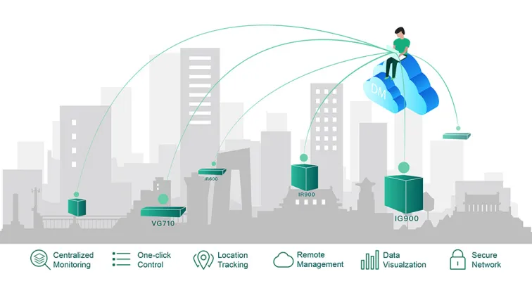
Figure 1-1 Device Manager Dashboard
Quick start with the platform: Register an account >> Configure a router or gateway and connect it to the platform >> Enable management of the router or gateway device.
2. Registration and Login
2.1 Registration
On a browser, enter https://iot.inhandnetworks.com/ to visit the official website of Device Manager. Click Register Account, enter an email account and relevant information, and click Submit. The authenticity of the email account will be verified. Please activate the account as instructed.
2.2 Login
After registration, log in to the platform with the registered email account and password. After login, choose Personal Center >> Settings, modify the login password and bind a phone number. Then, the phone number and the verification code or the phone number and password can be used for login. The phone number can also be used for recovering the password.
If access to Device Manager or InConnect via InHand Cloud Service is required, click here.
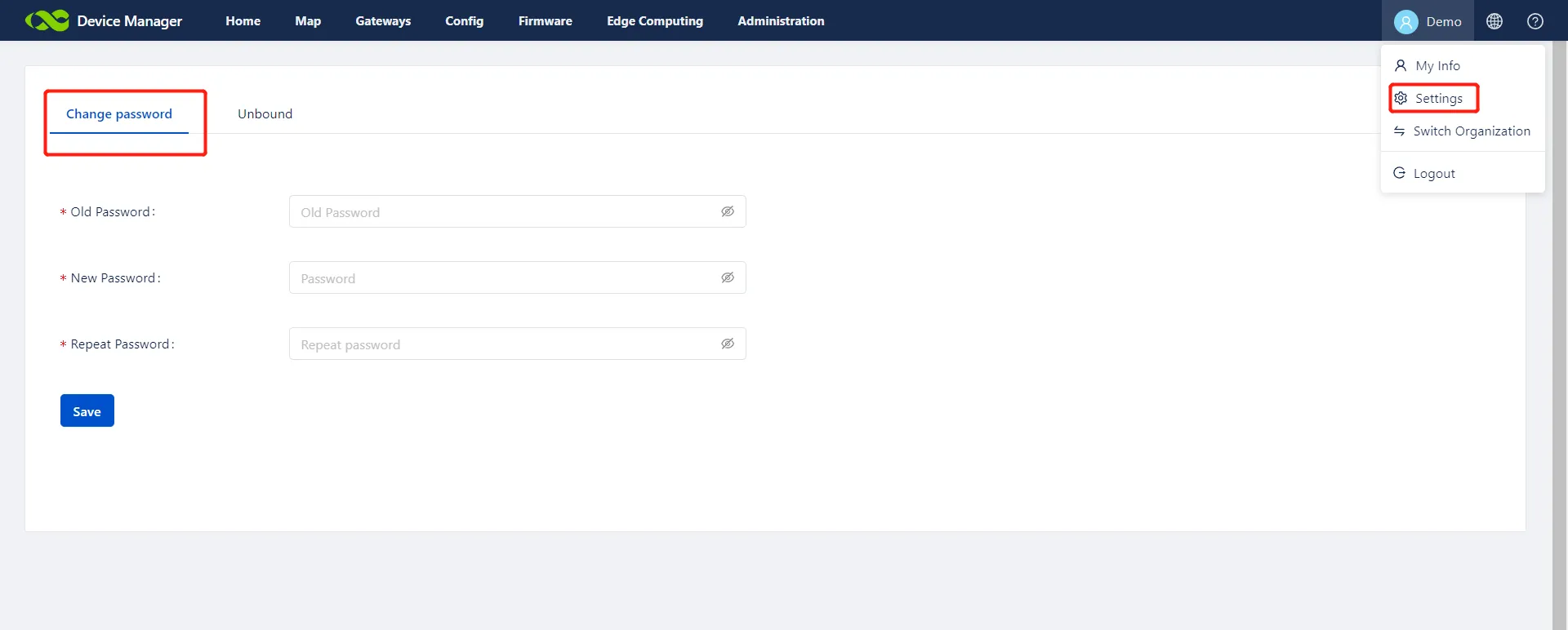
Figure 2-1 Device Manager Login Interface
3. Connect Gateway Devices to DM
The following devices are supported for management on the Device Manager platform: InRouter200, InRouter300, InRouter600, InRouter900, InGateway900, InGateway500, InVehicleG710, InVehicleG810. After connection configuration is made on the device, a new device data record is automatically added to DM. Administrators do not need to manually record the device data on DM. The following describes the details.
Configure the router to connect it to DM. Before configuration, make sure that the router has been connected to the network. For more information about networking operation, see the appendix.
3.1 Connect IR300/IR600 to DM
After connecting the router to a PC, visit 192.168.2.1 or 192.168.1.1 on a browser, enter the login account adm and password 123456 to log in to the device web page. On the web page, choose Services >> Device Manager, choose Service Type as Device Manager and Server as iot.inhandnetworks.com and enter the email account used for registration with DM in Registered Account:
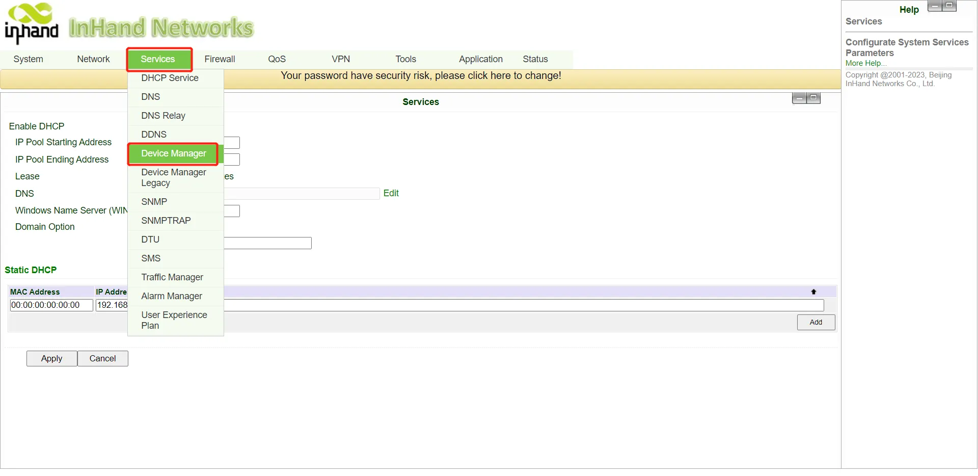
Figure 3-1 Device Manager Service Configuration (1)
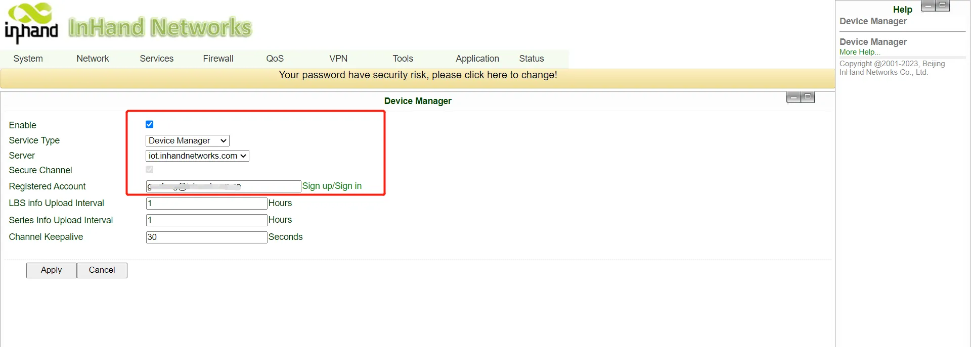
Figure 3-2 Device Manager Service Configuration (2)
[!NOTE] The page varies with the device firmware version. The actual page shall prevail.
After the router is configured, a gateway data record is automatically added to the Gateways page on DM. When the router status is Online, the device has been connected to DM:
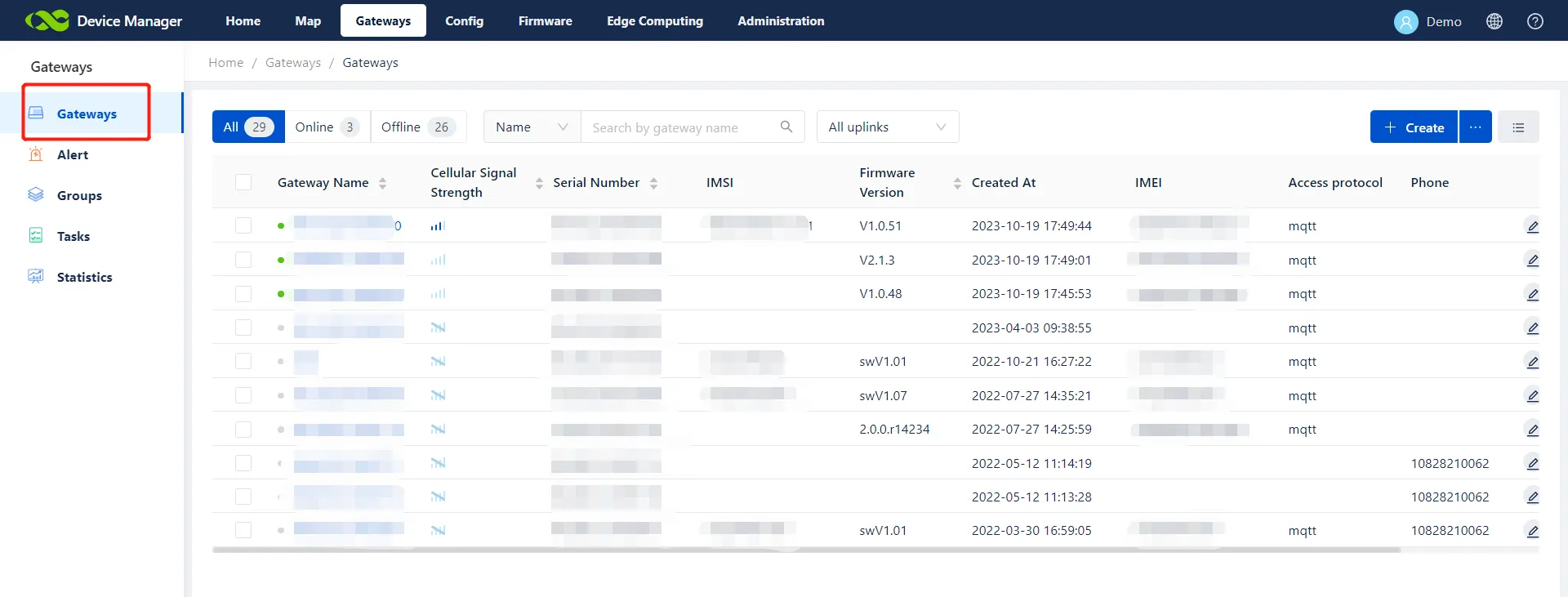
Figure 3-3 Gateway Online Status
3.2 Connect IR900/VG710 to DM
After connecting the router to a PC, visit 192.168.2.1 or 192.168.1.1 on a browser, enter the login account adm and password 123456 to log in to the device web page. On the web page, choose Administration >> Device Manager, set Service Type to Device Manager, select iot.inhandnetworks.com from Server Address, and enter the email account used for registration with DM in Registered Account:
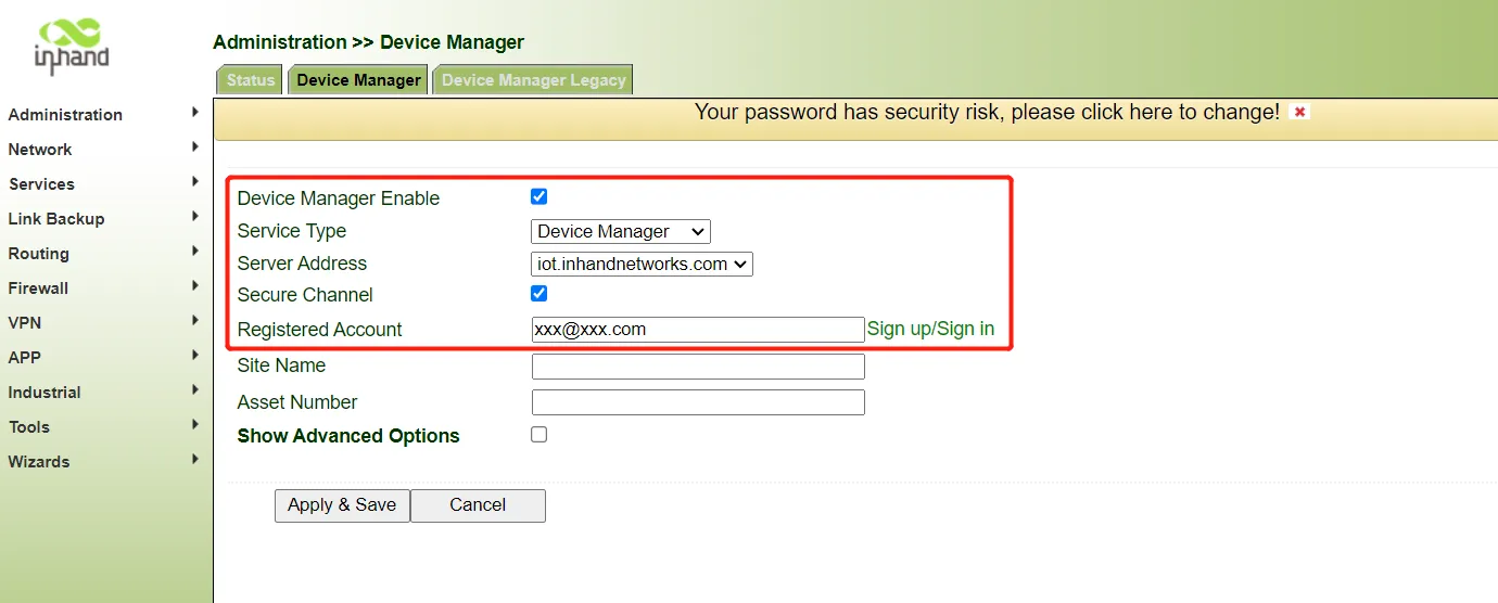
Figure 3-4 Connecting IR900/VG710 to DM
Click Apply & Save. If the status is Connected, the device has been connected to DM:
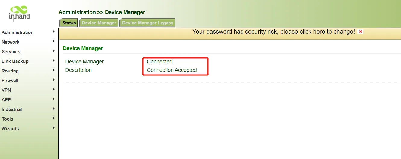
Figure 3-5 Connection Status
[!NOTE] The page varies with the device firmware version. The actual page shall prevail.
After the router is configured, a gateway data record is automatically added to the Gateways page on DM. When the router status is Online, the device has been connected to DM.
3.3 Connect IG500/IG900 to DM
After connecting the router to a PC, visit 192.168.1.1 on a browser, enter the login account adm and password 123456 to log in to the device web page. On the web page, choose System >> InHand Cloud, on the tab page of InHand Device Manager, set Server Address to iot.inhandnetworks.com, and enter the email account used for registration with DM in Registered Account:
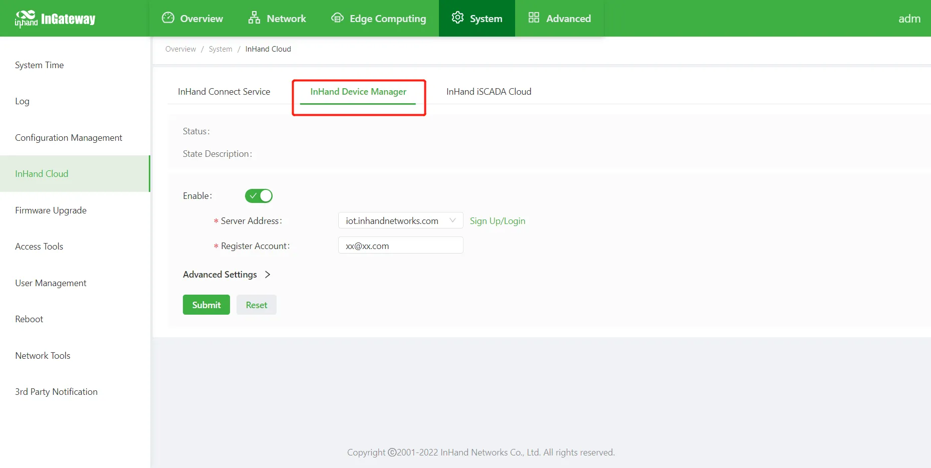
Figure 3-6 Connecting IG500/IG900 to DM
3.4 Add Gateway to DM
As mentioned above, after the router is configured, a gateway data record is automatically added to the Gateways page on DM. Administrators can manually add the data before configuring the router. The status of the manually added gateway is Offline. After the gateway can be connected, its status changes to Online.
3.4.1 Add a single gateway
- Choose Gateways >> +. Enter a gateway name in Gateway Name, enter the serial number in Serial Number. To view the serial number, on the home page, choose Administration >> System >> Status or Gateway Nameplate S/N, and then click OK.
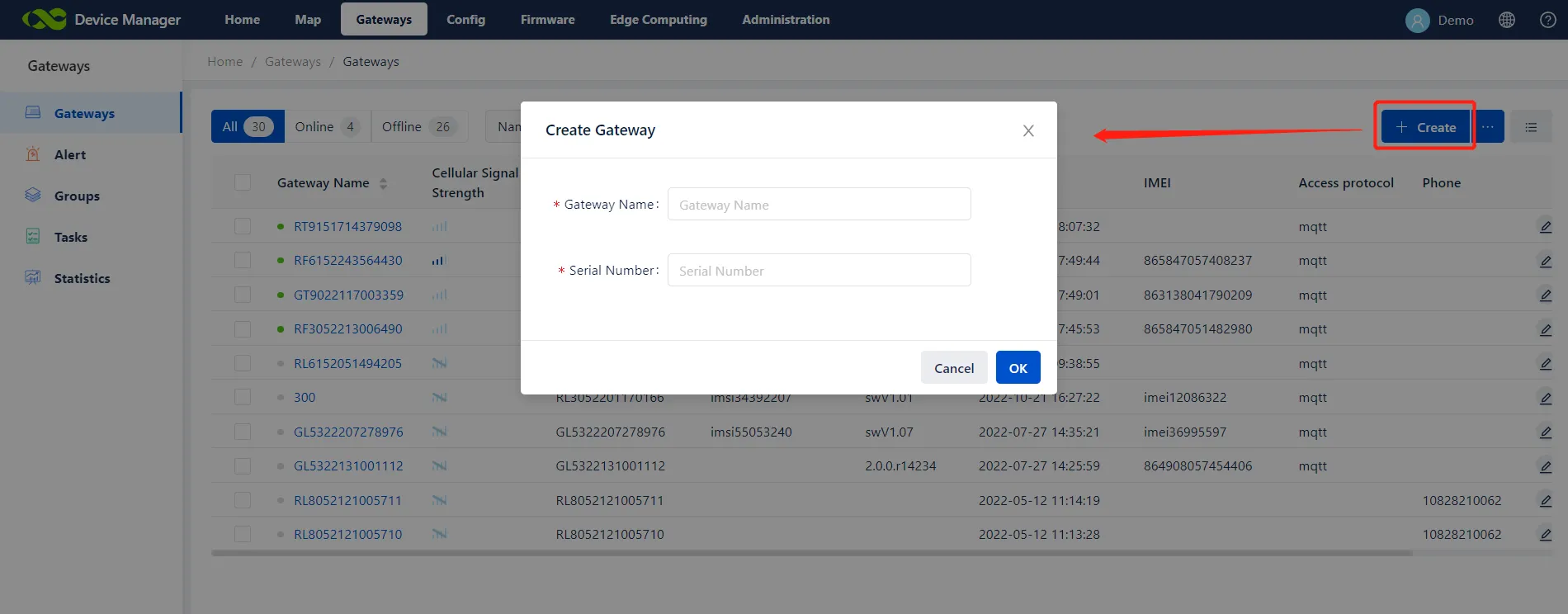
Figure 3-7 Adding a Single Gateway
- Return to the Gateways page. The device is added. If the dot before the gateway name turns green, the device is online and connected to DM and the network. If the dot is gray, the device is offline and disconnected from the network. DM cannot manage and monitor offline devices.
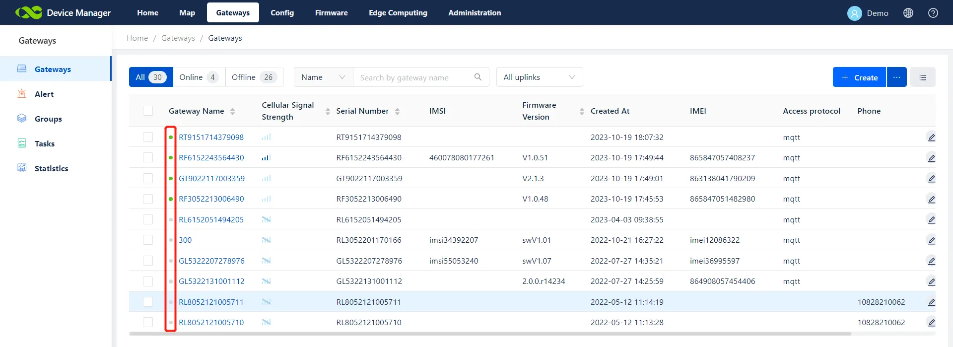
Figure 3-8 Gateway Online/Offline Status Indicators
3.4.2 Add gateways in batches
- Choose Gateways >> Import >> Download Template, enter the gateway information, and save the template. Click Select File, select the saved template, and click OK. Administrators can choose to override the import or import the gateway into a group when importing the file.
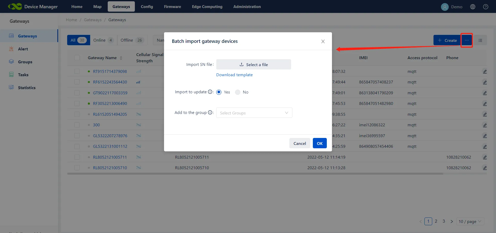
Figure 3-9 Importing Gateways in Batches
- Return to the Gateways page to view the imported devices.
4. Gateway Management
After a gateway is connected to DM, administrators can manage the device on DM, enabling functions such as device asset management, configuration update, firmware upgrade, position tracking, running monitoring, and operation command monitoring.
4.1 Basic Management
4.1.1 Information Management
In the Details Information section of the Gateways page, administrators can manage key information of the gateway, including basic information (such as the model, serial number, IP address, RSSI, and IMSI), running information (such as traffic statistics and online statistics), and control information (such as task list). Devices connected to DM regularly report their traffic, online status, and other running information to DM for real-time monitoring and analysis.
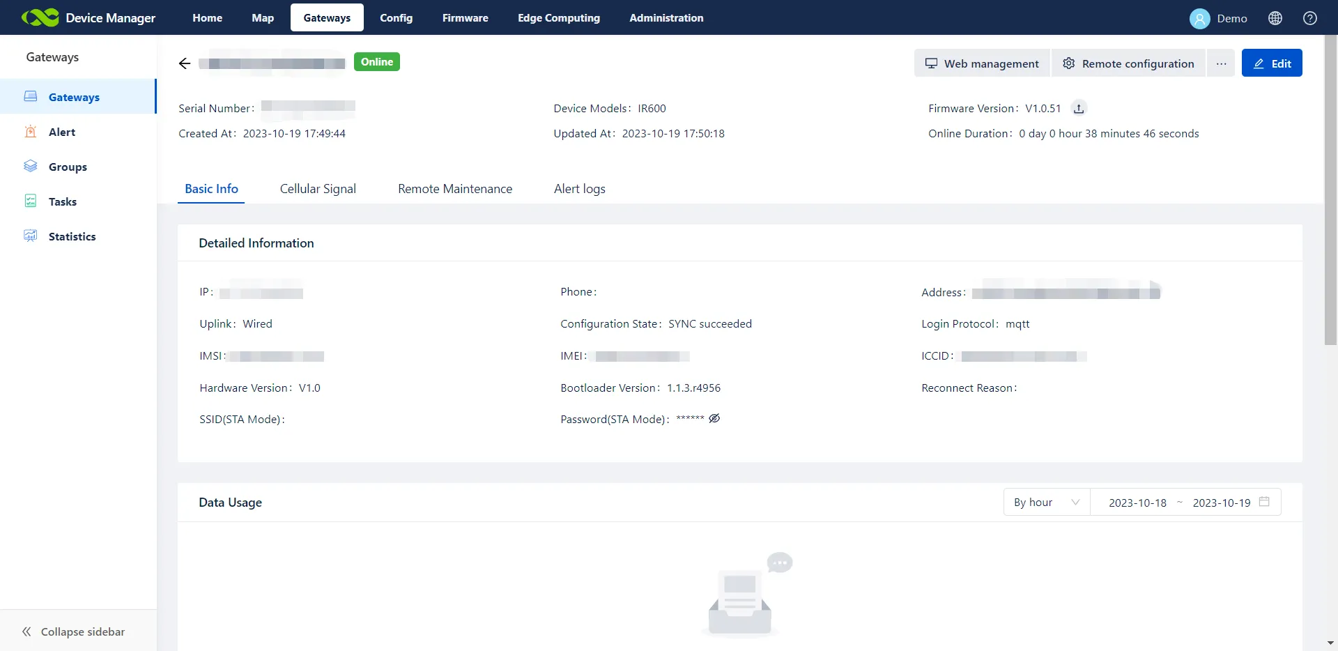
Figure 4-1 Details Information Page
4.1.2 Remote Web Access
- On the Gateways or Device Details page, click the Web Management icon to go to the Web Management page of the gateway. On this page, administrators can directly modify the device configuration locally. This function is only applicable for online devices.
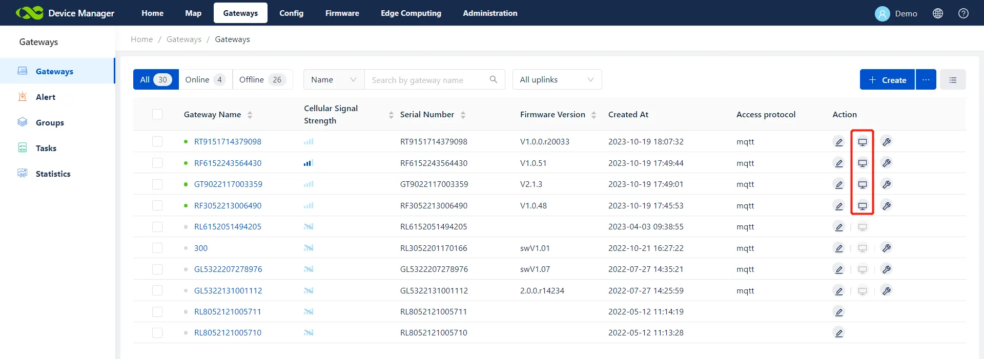
Figure 4-2 Web Management Icon
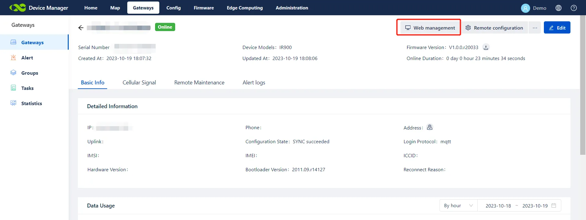
Figure 4-3 Remote Web Management Interface
- Enter the username and password to go to the Web Management page of the gateway, and then remotely operate and control the device through commands.
4.1.3 Update Configuration
Administrators can only update the configuration of online devices.
On the gateway details page of an online device, click Remote Configuration. Edit and update the device configuration and then click Deliver. The device configuration is remotely updated, and a task record is generated in the task list on the details page. The task status is updated in real time to reflect the execution status.
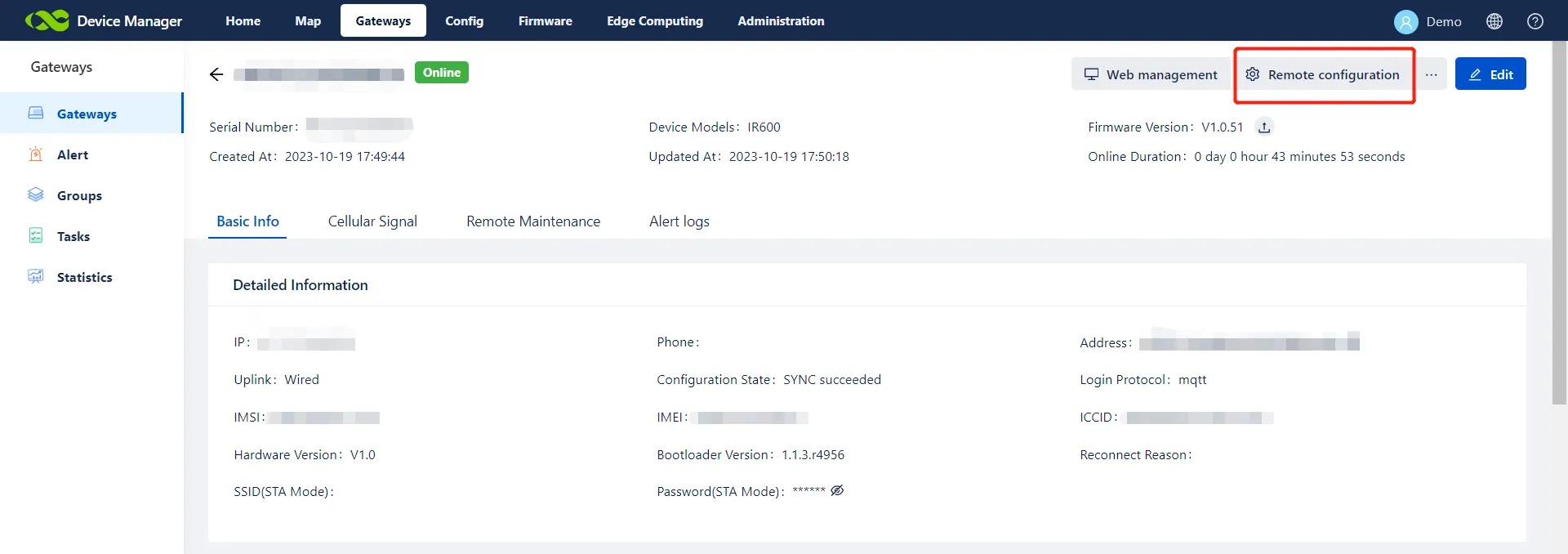
Figure 4-4 Remote Configuration Editor
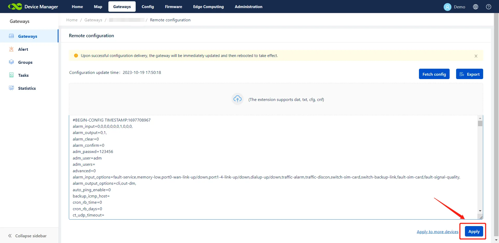
Figure 4-5 Task Execution Status
4.1.4 Upgrade Firmware
On the device details page, click the edit icon  next to Firmware Version, and upload a file. After the file is uploaded, a task record is generated in the task list on the details page. The task status is updated in real time to reflect the execution status.
Online devices execute the upgrade task immediately, while offline devices will execute the upgrade task after they are online again.
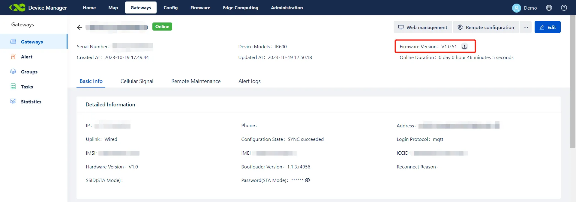
Figure 4-6 Firmware Upgrade Interface
4.1.5 Forced Offline
When configuration delivery and firmware upgrade fail multiple times, administrators can try to force a gateway offline, connect it to DM again, and then try to deliver the configuration and upgrade the firmware again.
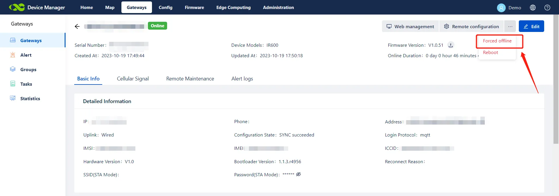
Figure 4-7 Forced Offline Option
4.2 Alerts
The Device Manager platform supports setting alerts to monitor some important events of the devices. When an event occurs, it can push SMS or email messages to specified users. The support of each device is subject to the information displayed on the interface. Taking IR600 for example, an offline alarm is used to perform operations.
- Configure alert rules: On the page of Gateways >> Alerts >> Alert Rules, click Add Rule, select devices, alert rules, and notification rules in the form as needed:
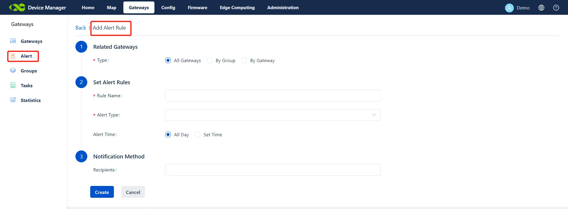
Figure 4-8 Configuring Alert Rules
- After the rule is added, click Save. The rule takes effect immediately; as shown in the figure, an offline alarm rule is configured for a gateway: When the gateway is offline for 10 minutes, the user's email will receive an alert email, and the alert messages will also be recorded on the Gateways >> Alerts >> Alert Logs page.
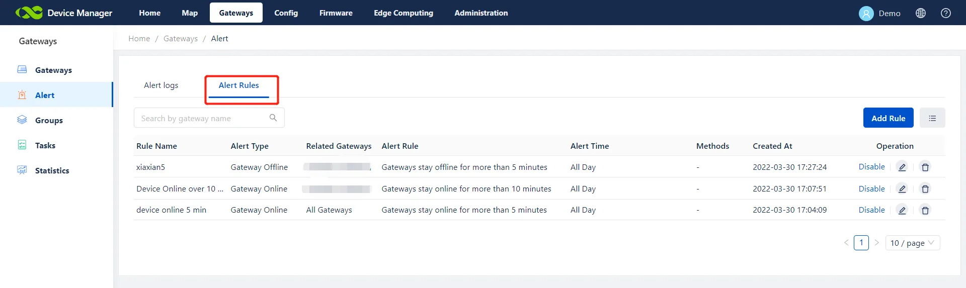
Figure 4-9 Alert Rule Activation
- For some specific alert types, administrators must enable alert reporting on the device before the alert takes effect. Take the IR600 for example: on the device WEB management page, visit the page Services >> Alarm Manager, select alarm type, select Device Manager as the alarm output, then click Apply.
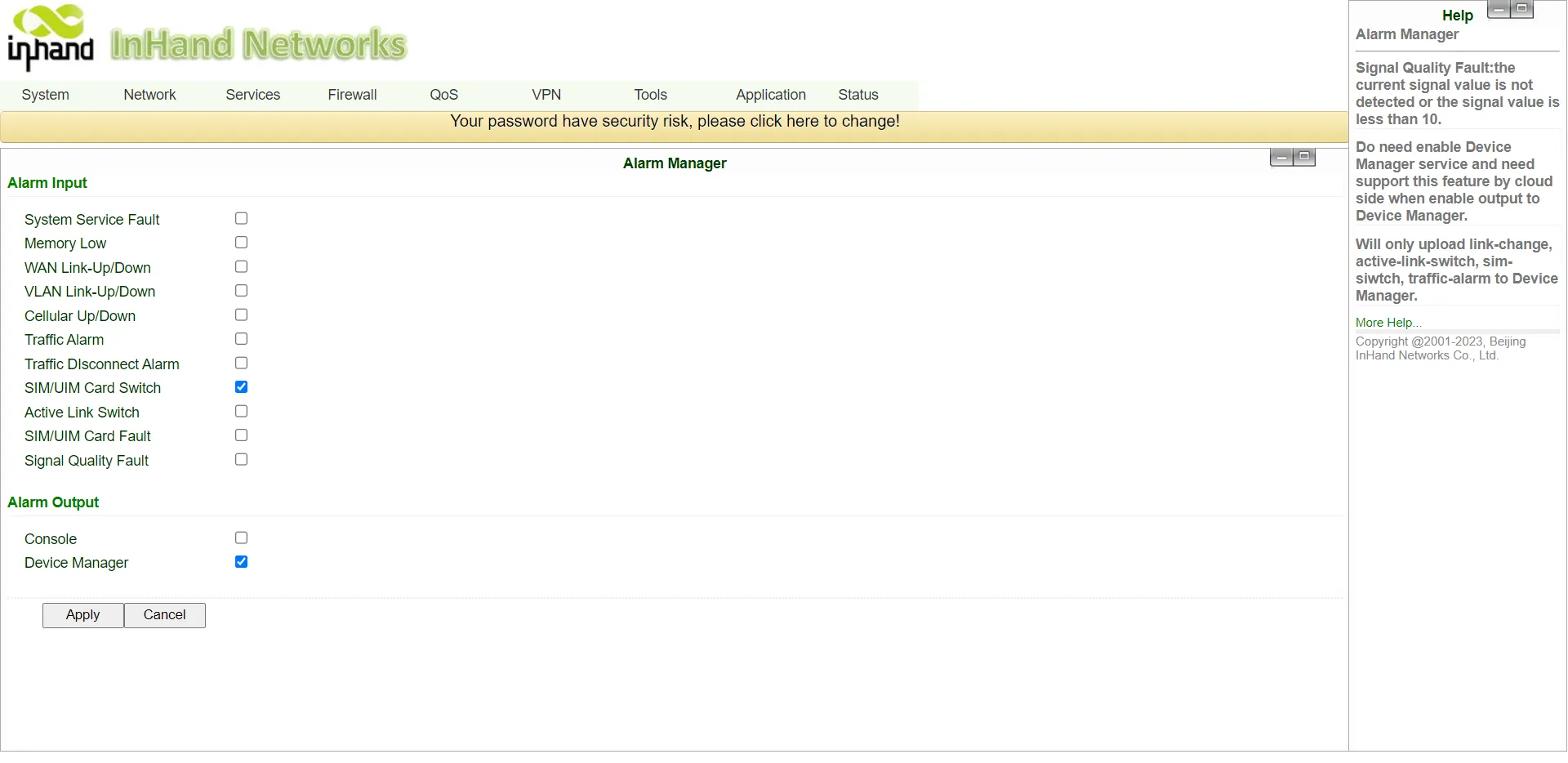
Figure 4-10 Enabling Local Alert Reporting
- After the application is successful, when the device has the above event, it will send an event message to the platform, and the user will receive an email or SMS alert message according to the settings. The following table lists the alert types of the platform and the device:
| Device Manager | The WEB management page of device |
|---|---|
| Gateway Online/Offline | For the monitoring item of the Device Manager platform, there is no such alert type on the local device. Trigger condition: The device establishes/disconnects a connection with the platform. |
| Hourly Traffic Alarm | The alarm type is "Traffic Alarm", and the traffic alarm threshold should be defined in the Services >> Traffic Manager section at the same time. After setting the required hourly, 24-hours (day) and monthly thresholds, the platform will send an alarm message when the specified alarm threshold is reached.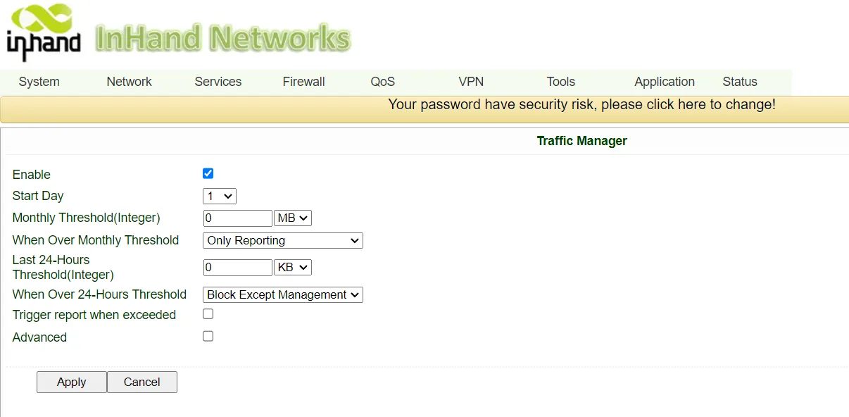 |
| Daily Traffic Alarm | See Hourly Traffic Alarm |
| Monthly Traffic Alarm | See Hourly Traffic Alarm |
| SIM Switch | Active Link Switch |
| Link Backup | Active Link Switch |
| Interface Up/Down | WAN Link-Up/Down, LAN Link-Up/Down, Dialup Up/Down |
| Power Type Switch | The local alert type corresponding to the device is "Power Supply Switch". Trigger conditions: 1. If the device is powered only by the battery and then the power adapter is plugged in, the "Switch to Adapter Power Supply" alert will be triggered. 2. If the device is already powered by the adapter and then the adapter is unplugged, the "Switch to Battery Power Supply" alert will be triggered. 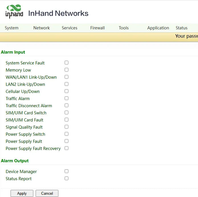 |
| Battery Fault | The local alert type corresponding to the device is "Power Supply Fault". Trigger condition: The battery of the device cannot be used normally for power supply. |
| Battery Fault Recovery | The local alert type of the corresponding equipment is "Power Supply Fault Recovery". Trigger condition: The battery fault has been resolved. |
4.3 Device Group Management
When the system has a great number of devices, administrators can group devices for centralized management in the Groups table. For example, devices can be managed by industry, clarifying the scenarios of each device. Abnormal devices can also be placed in the same group for centralized management. When the device error is removed, the device can be moved out of the group.
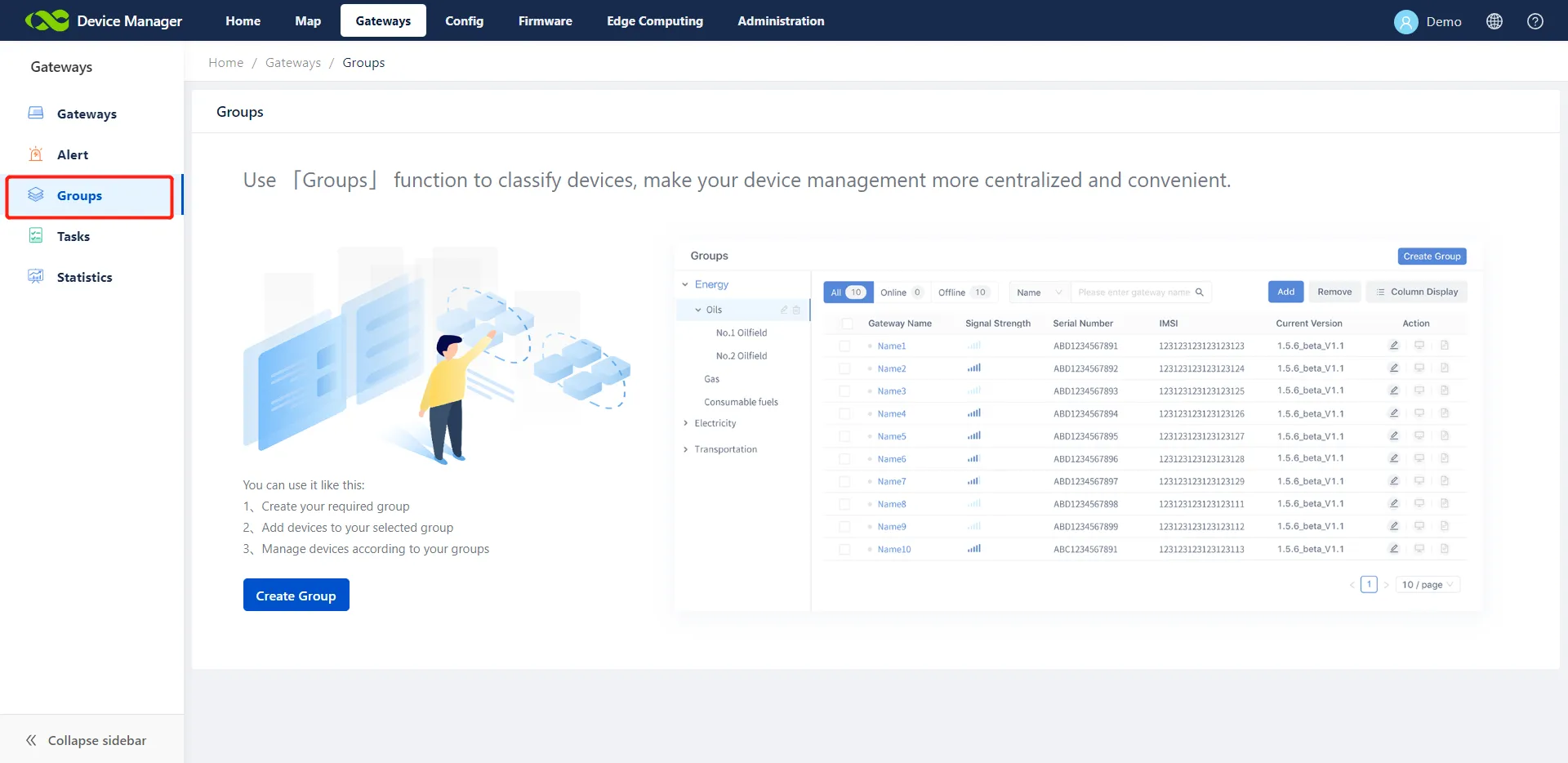
Figure 4-11 Device Group Management
The following describes the details:
- Click Create Group and enter the group name and other information:
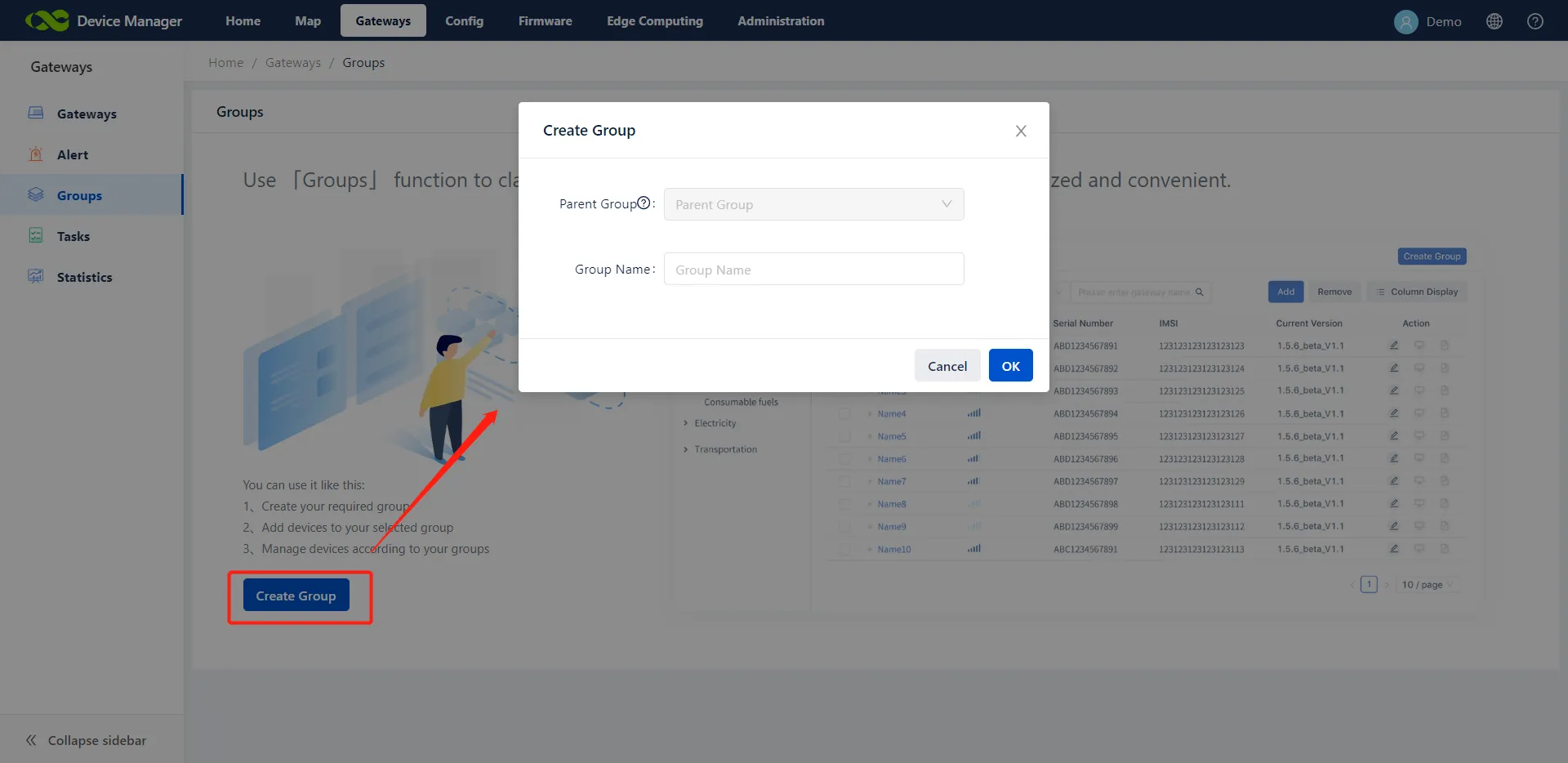
Figure 4-12 Creating a Group
- After the group is created, administrators can add devices to the current group:
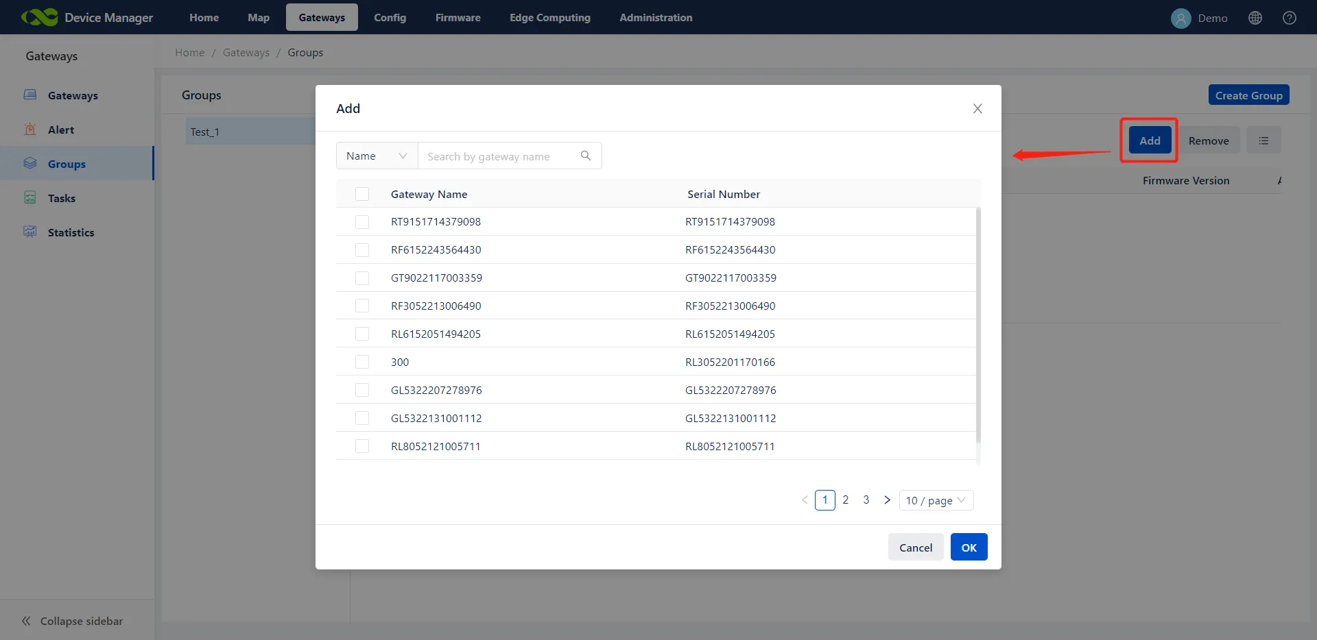
Figure 4-13 Adding Devices to a Group
- If an added group has changed, select the group and then move it out of the current group.
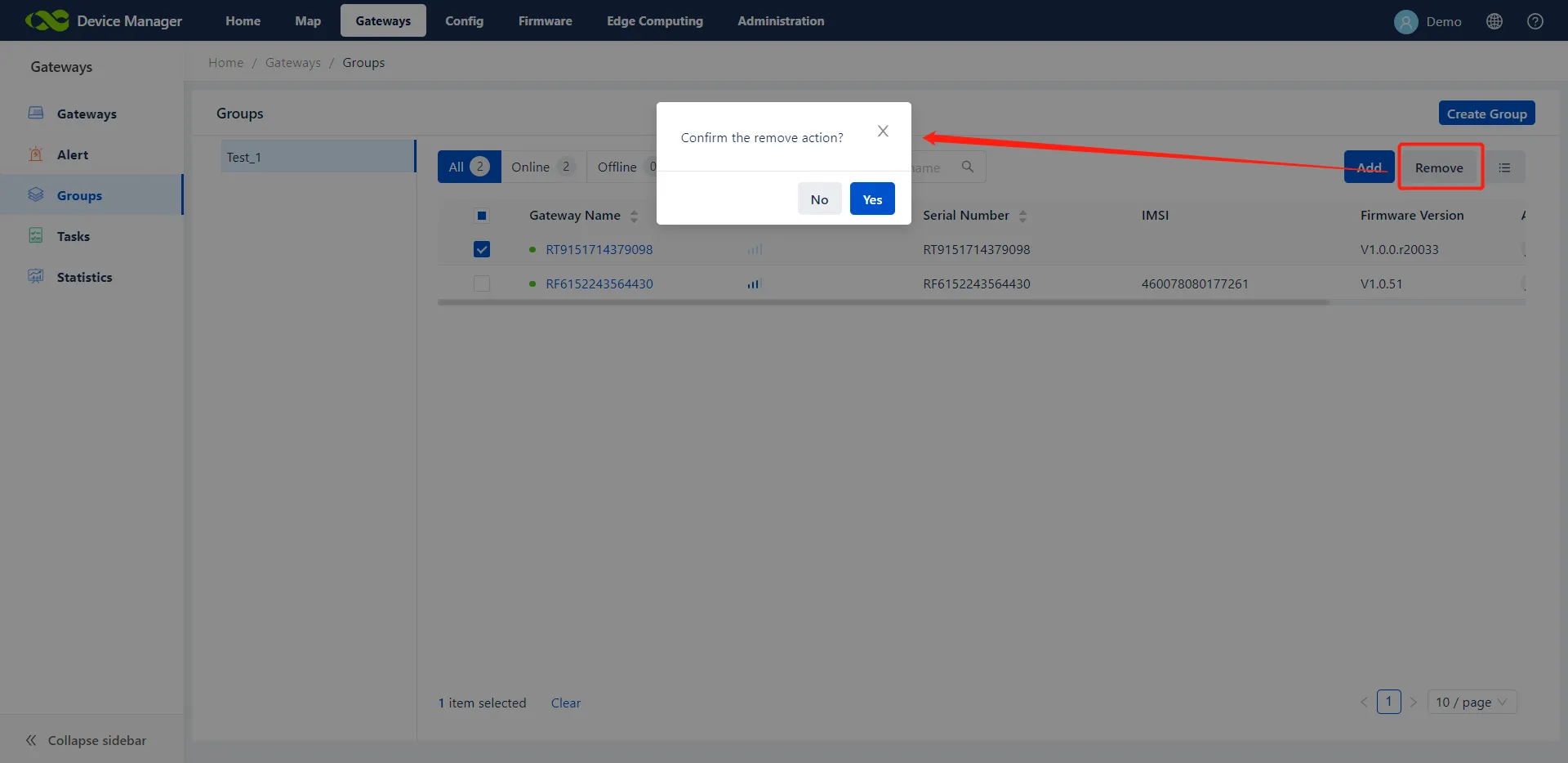
Figure 4-14 Moving a Group
Administrators can create groups of multiple levels based on service demands to manage devices by level.
4.4 Position Tracking
The Map page displays the real-time position and online status of the gateway. After clicking the device icon on the map, the device basic information is displayed. Then, administrators can click the gateway name to view the device details.
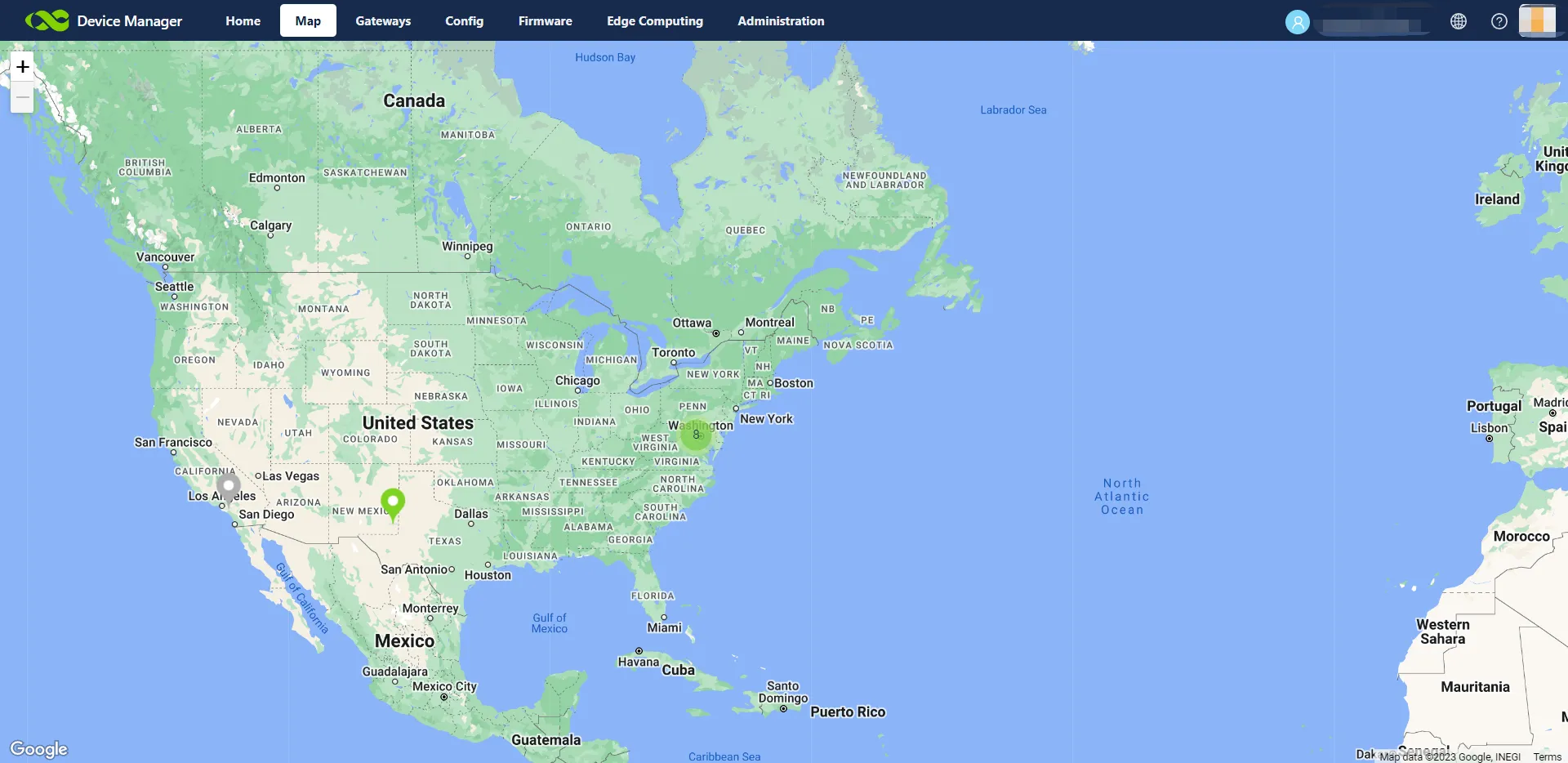
Figure 4-15 Map Position Tracking
4.5 Gateway Running Monitoring
- On the Gateways >> Statistics page, administrators can view online duration statistics and traffic usage of a device and export the list of its online duration and traffic usage.
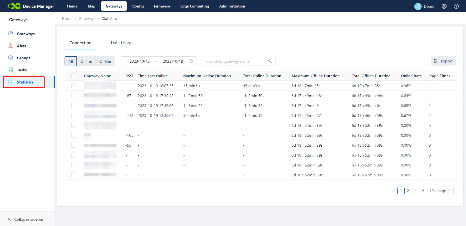
Figure 4-16 Gateway Statistics Page
- Click the device. The device status bar chart is displayed.
- Online: The device is connected to DM.
- Offline: The device is disconnected from DM.
- Abnormal: When the statistical period is less than three days, if the status changes for more than three times in two hours, it is abnormal. When the statistical period is more than three days, if the status changes for more than three times in one day, it is abnormal.
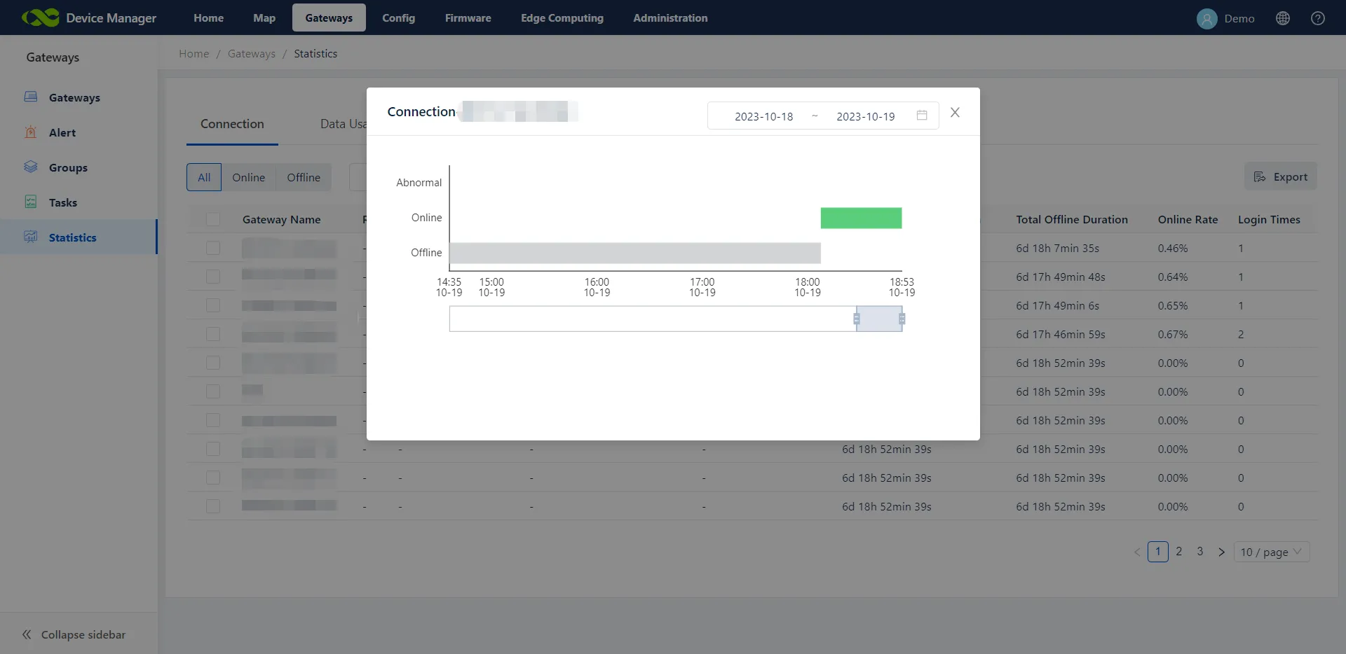
Figure 4-17 Device Status Bar Chart
4.6 Operation Command Monitoring
On the page of Gateways >> Tasks, administrators can view the execution status of the tasks sent from DM to devices. In the Action column, click to re-execute a task or cancel an in-progress task.
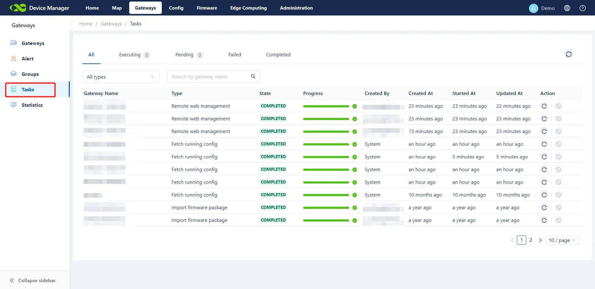
Figure 4-18 Operation Command Tasks
5. Update Gateway Configurations in Batches
When a large number of devices are connected to DM, it takes a great amount of time to update the configuration device by device. Administrators can update the configuration in batches on the Config page. The following describes the details:
- Choose Gateways >> Config >> + >> Select File. Select a configuration file (which can be exported from the Web Management page of the gateway, edited, and then applied), enter a name in Config Name, enter the model in the template in Device Models, and then click OK.
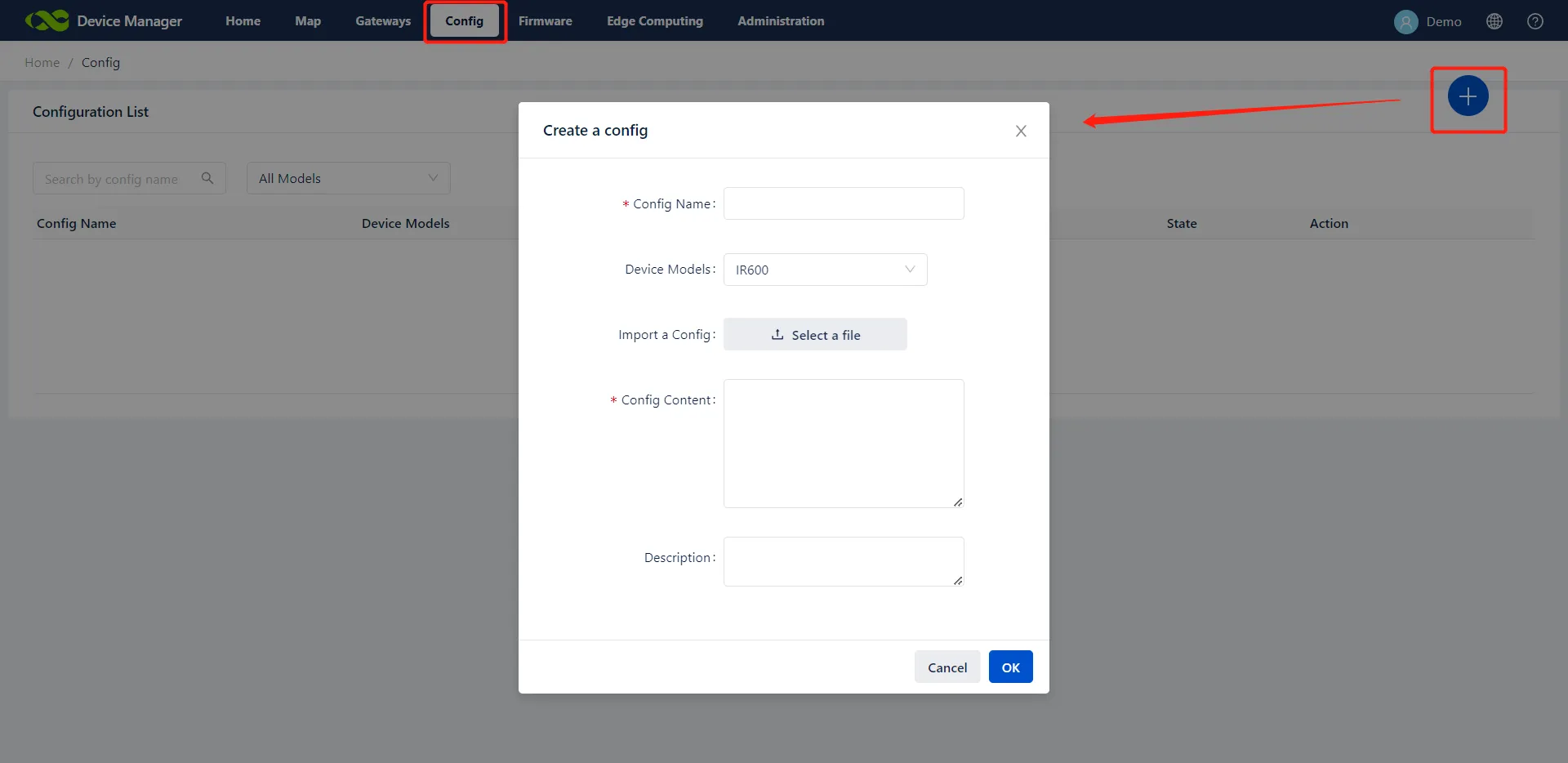
Figure 5-1 Adding a Batch Configuration
- Select the device to which the configuration will be delivered and click OK.
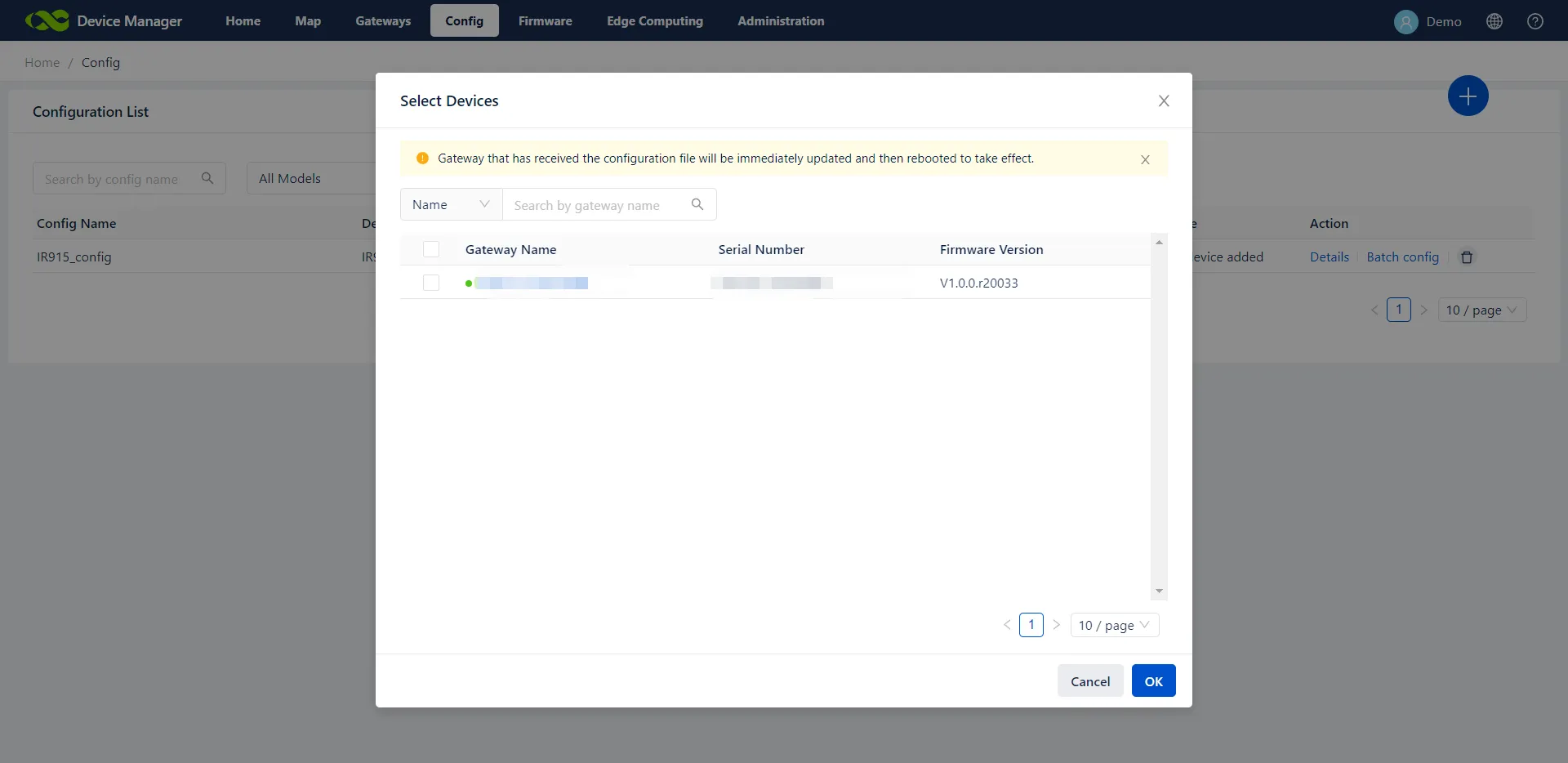
Figure 5-2 Selecting Target Devices for Configuration
- Return to the configuration list, click View details to view details of the current configuration, such as its update progress and status:
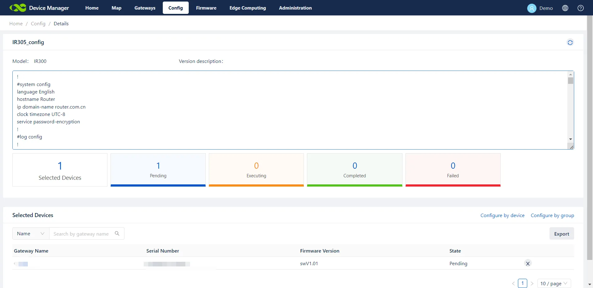
Figure 5-3 Batch Configuration Status Details
6. Upgrade Gateway Firmware in Batches
When a large number of devices are connected to DM, it takes a great amount of time to upgrade the firmware device by device. Administrators can upgrade the firmware in batches through the Firmware page. The following describes the details:
- Choose Firmware >> +. Select a gateway firmware and click OK.
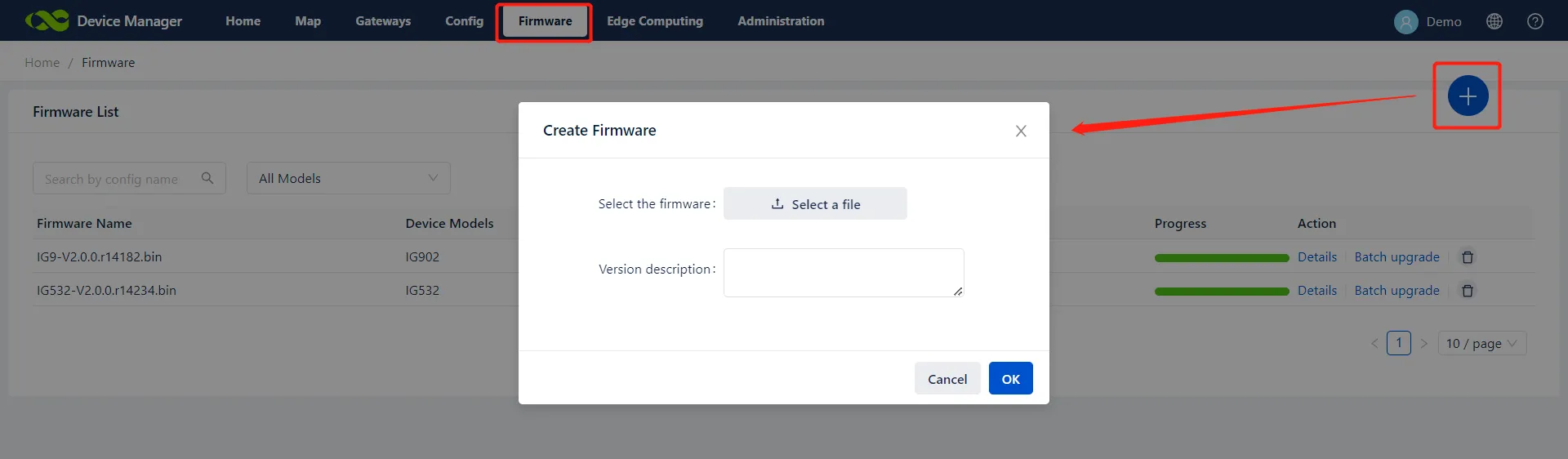
Figure 6-1 Adding Firmware for Batch Upgrade
- Select the device for which the firmware will be upgraded and click OK.
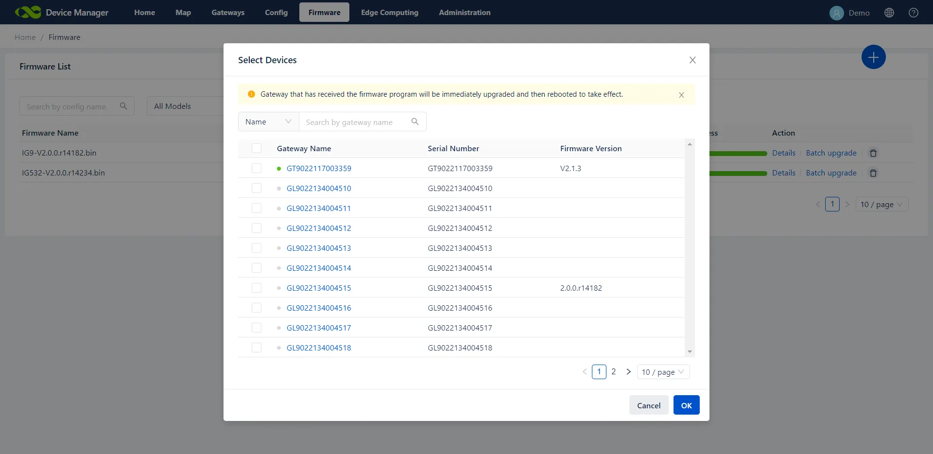
Figure 6-2 Selecting Target Devices for Firmware Upgrade
- Return to the firmware list, click Details to view the details of the current firmware, such as its upgrade progress and status:
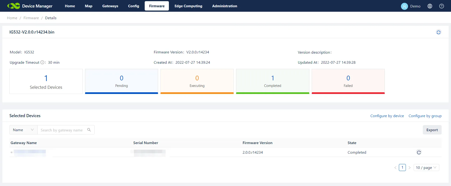
Figure 6-3 Batch Firmware Upgrade Status Details
7. Edge Computing
As one of the core features of the Edge Gateway, the edge computing functions of the DM platform are mainly applied to gateway devices with edge computing features, such as IG500, IG900, and VG series.
7.1 Edge Agent
Edge engine is the operating environment for edge applications of the gateway device. It integrates the Python, Azure IoT Edge, and Docker programming development environment, and can strengthen the ability of edge applications to cooperate with the cloud. Administrators can flexibly customize applications according to business needs. The edge engine must be installed before installing edge applications.
- On the page of Edge Agent, click Add Edge Agent, select the edge SDK from InHand Networks.
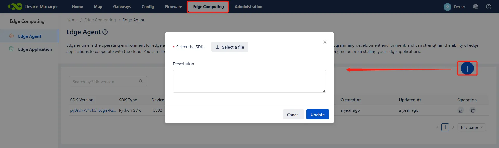
Figure 7-1 Adding Edge Agent SDK
- Then click SDK Version to view more information, click Deploy, and select Gateways to install this SDK.
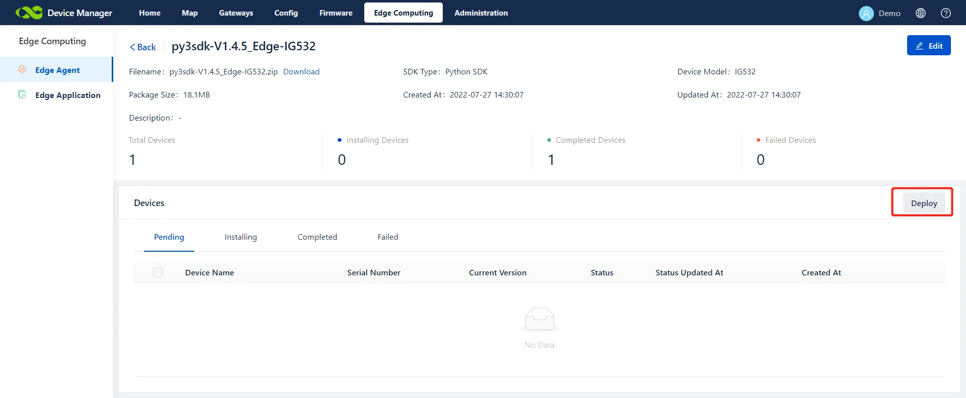
Figure 7-2 Deploying Edge SDK
- On the installation page, the detailed progress status of each installation task is displayed, including Pending, Installing, Completed, and Failed. For failed tasks, administrators can view the failure reason in the task list.
7.2 Edge Application
- Click Add Applications, import the APP to be installed.
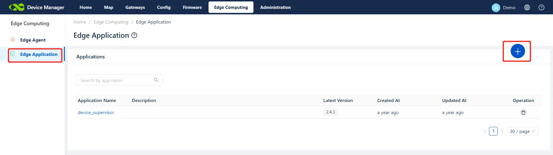
Figure 7-3 Adding Edge Applications
-
Then click Application Name to view the details. If there is a version update, administrators can also upload a new version here.
-
Click App Deploy, select Deploy, and select the required device. The system will automatically send the APP to these devices to perform the upgrade. On the installation page, the detailed progress status of each installation task is displayed, including Pending, Installing, Completed, and Failed. For failed tasks, administrators can view the failure reason in the task list.
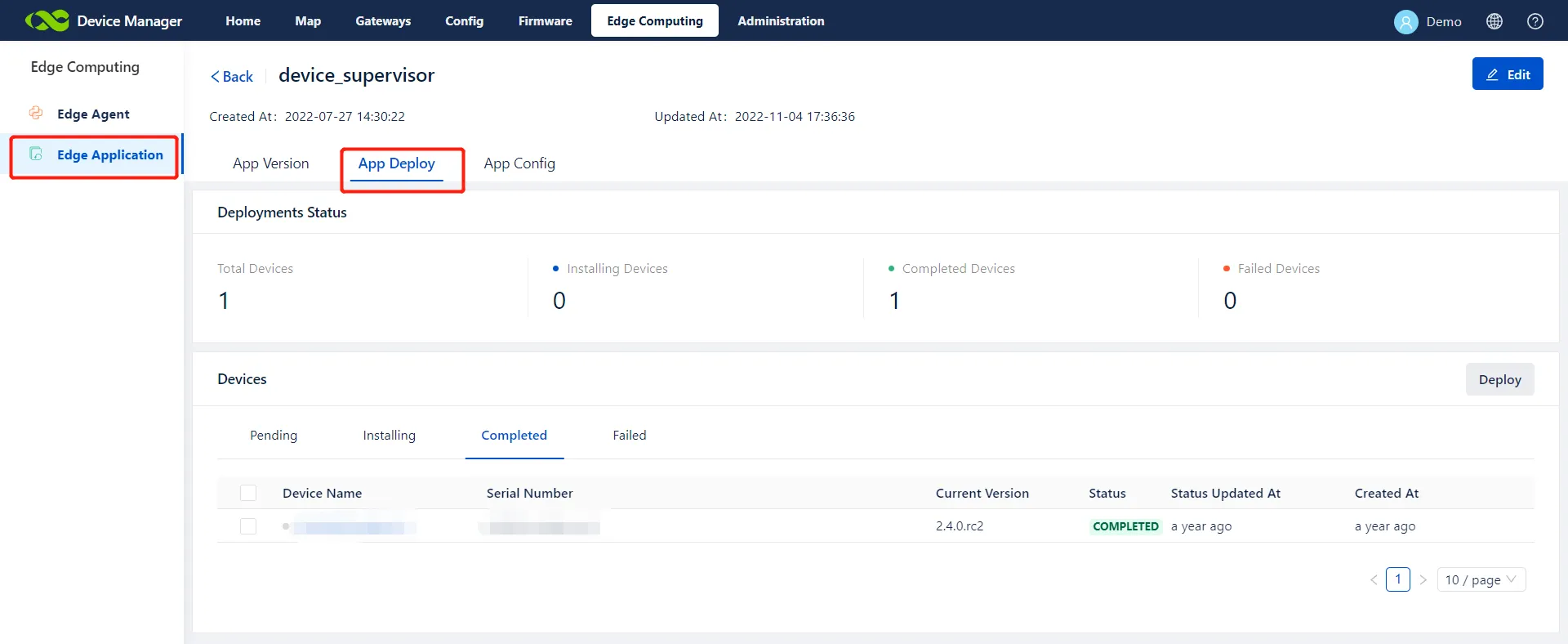
Figure 7-4 Deploying Edge Applications
- Click App Config to maintain the app configuration or view the configuration details and the update records of the gateway configuration in detail.
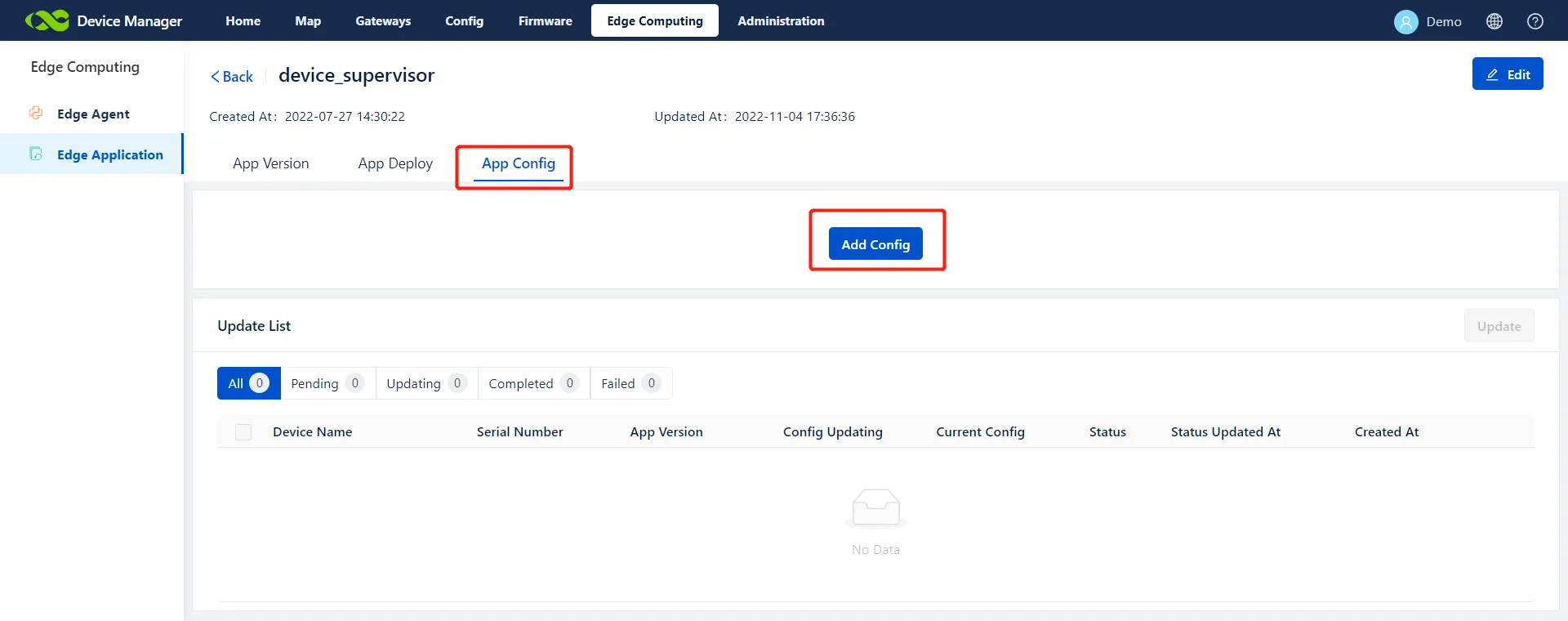
Figure 7-5 Edge Application Configuration
7.3 Gateway Details
-
In the details of a gateway with edge features, administrators can view the current status of the device's SDK and APP installation history.
-
Administrators can directly update the SDK and APP of a single gateway in the gateway details. The updated SDK and APP need to be added in the Edge Agent and Edge Application in advance.
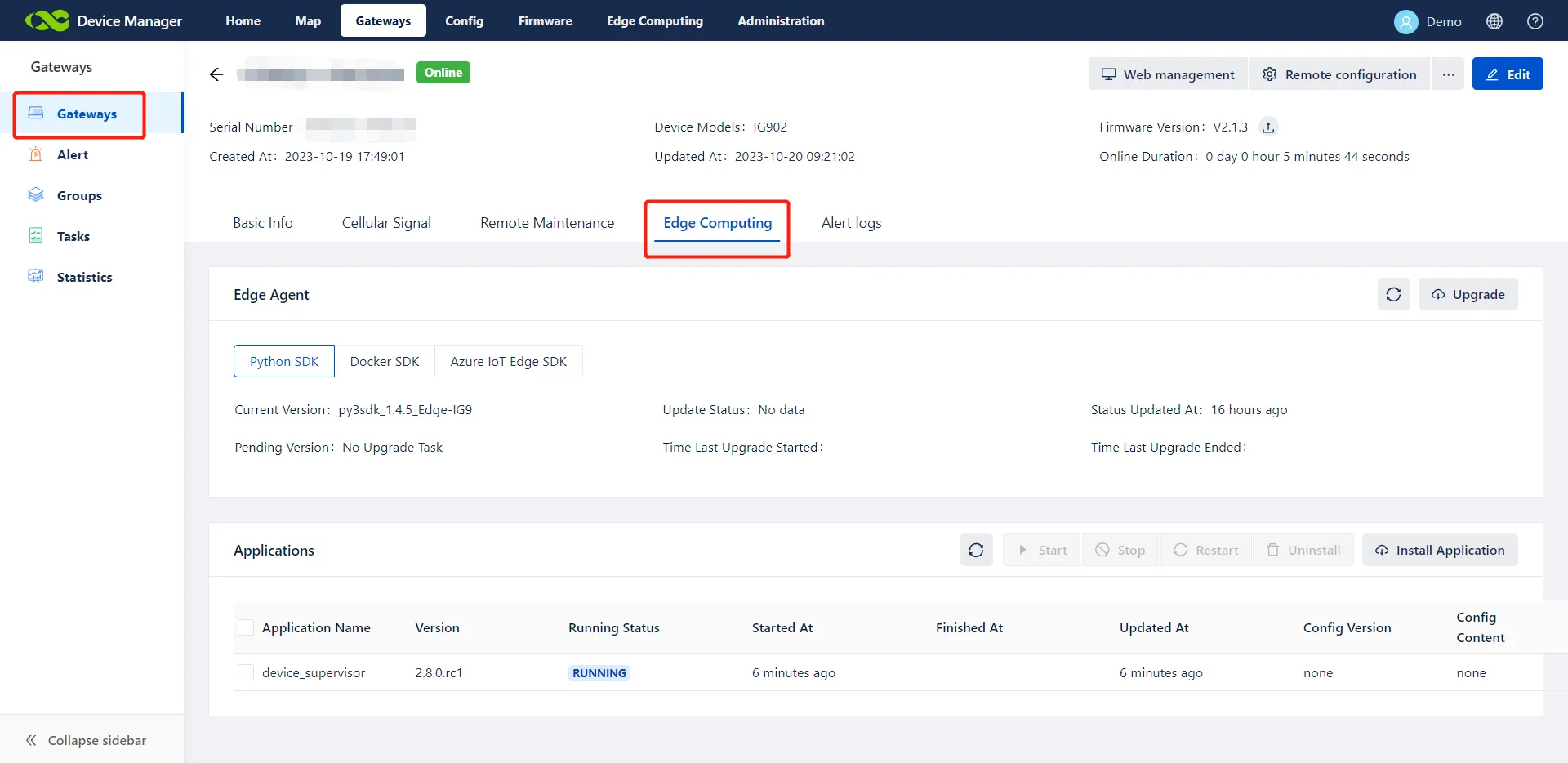
Figure 7-6 Edge Features in Gateway Details
8. System Management
8.1 User
8.1.1 Add a User
To manage devices through multiple users, administrators can add multiple accounts in the Users list, and grant different roles and permissions to different accounts for permission security control.
The system roles and their permissions are as follows:
| Function Page | Organization Manager | Device Manager | Device Monitor | |
|---|---|---|---|---|
| Home | √ | |||
| Map | √ | √ | √ | |
| Gateways | Gateways | √ | √ | √ |
| Alert | √ | √ | √ | |
| Groups | √ | √ | √ | |
| Tasks | √ | √ | √ | |
| Statistics | √ | √ | √ | |
| Config | √ | √ | ||
| Firmware | √ | √ | ||
| Edge Computing | Edge Agent | √ | ||
| Edge Application | √ | |||
| Administration | Users | √ | ||
| Access Control | √ | |||
| Company Info | √ | |||
| Operation Log | √ |
The operation is described below:
Choose Administration >> Users >> +, and add a user. The system automatically sends the password to the email account of the new user. The new user can use the email account and the password in the email to log in to DM.
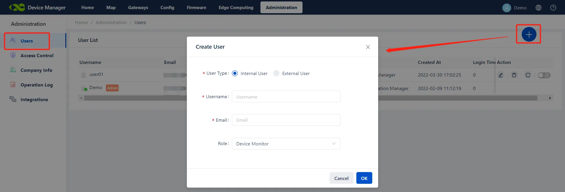
Figure 8-1 Adding a New User
8.1.2 Delete a User, Reset User Password, and Lock a User
- Delete user: Used to permanently remove a user.
- Reset password: Used to reset the password for a user. The new password is sent to the login email account of the reset user through email.
- Lock user: After a user is locked, they cannot log in to DM.
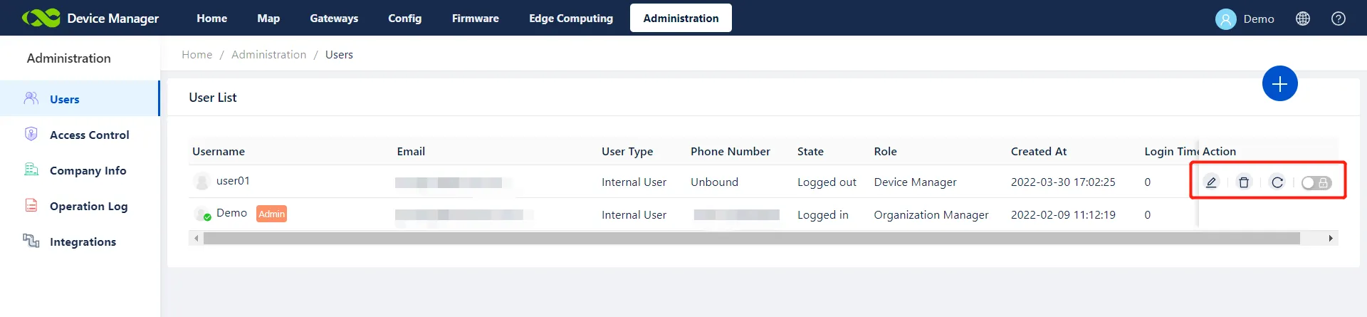
Figure 8-2 User Management Actions
8.2 Access Control
When the system has multiple users, devices, and groups, for secure device management and control, administrators can grant the management permissions of gateway devices and groups for each user in the Access Control list.
The Access Control module is used to divide the users' permission to view and manage gateway devices and groups. It allows customization of multiple permission groups. Gateway devices and groups in each permission group can only be viewed and managed by users in the current group.
Example: User A has 120 devices, 50 in California and 50 in Florida. Two persons are required to manage these devices separately, wherein Tom manages the 50 devices in California, and Mary manages the 50 devices in Florida.
Procedure: The administrator creates two permission groups on the Access Control page, assigns Tom and the 50 devices in California to one permission group, and assigns Mary and the 50 devices in Florida to the other permission group. The remaining 20 devices are placed in another permission group.
Specific functions: 1. New non-admin users are grouped into "Unallocated" by default. They can view all ungrouped devices by default. 2. Newly added devices and groups are grouped into "Unallocated" by default, and all users can view them. 3. Users in "Unallocated" can view all unallocated devices and groups. 4. Users in a custom group can view the devices in the current access control group and the devices in the "Unallocated" group. 5. Users in a custom group can view the groups in the current access control group and the groups in the "Unallocated" group. 6. The organization administrator (admin) does not participate in the permission grouping, and can view all device data. 7. A user can be divided into multiple groups. 8. A device and a group can only be divided into one group. 9. If a group is not in the same permission group as the devices in the group, users in the permission group in which the device is located can see the device but not the group or other devices in the group.
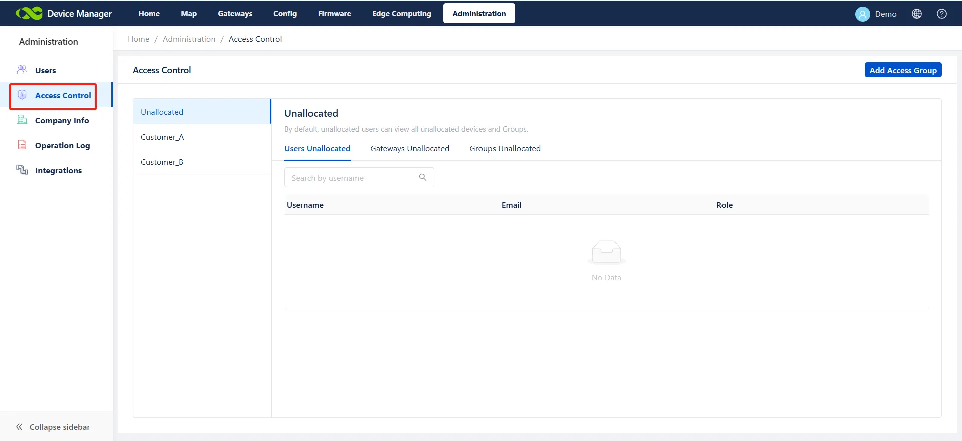
Figure 8-3 Access Control Interface
Creating a permission group:
Step 1: Choose Access Control >> Add Access Group. Enter a name for the permission group and click OK.
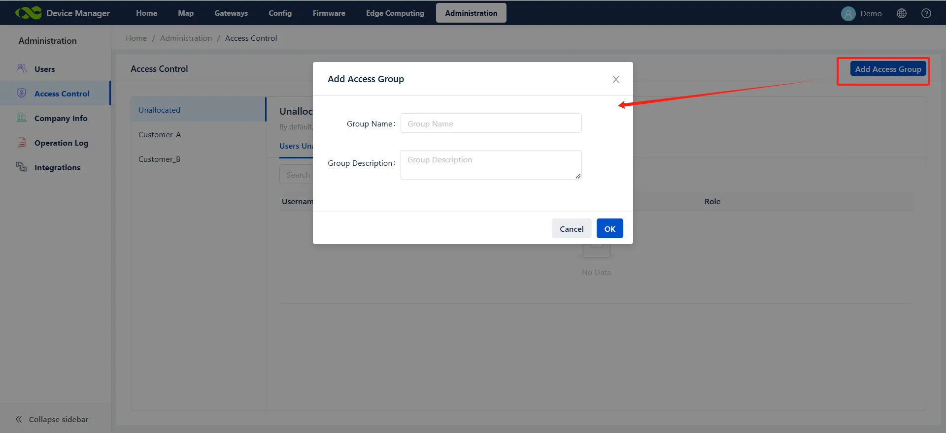
Figure 8-4 Creating a Permission Group
Step 2: Allocate users for the created permission group. Choose User Included >> Add Users to Group, select users, and then click OK.
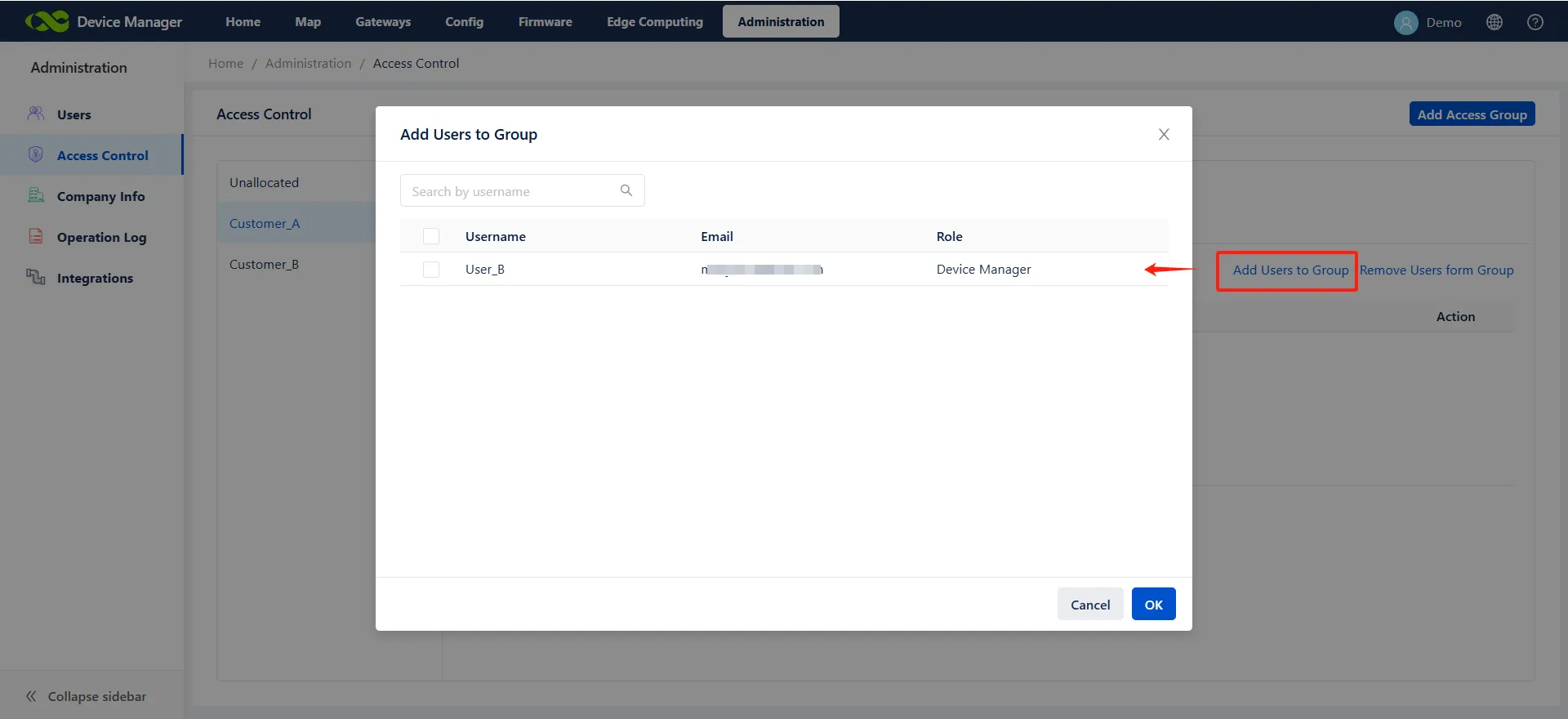
Figure 8-5 Allocating Users to a Group
Step 3: Allocate gateways to the created permission group. Choose Gateway Included >> Add Gateways to Group, select gateways, and then click OK. Devices in the permission group can only be viewed and managed by users in this permission group.
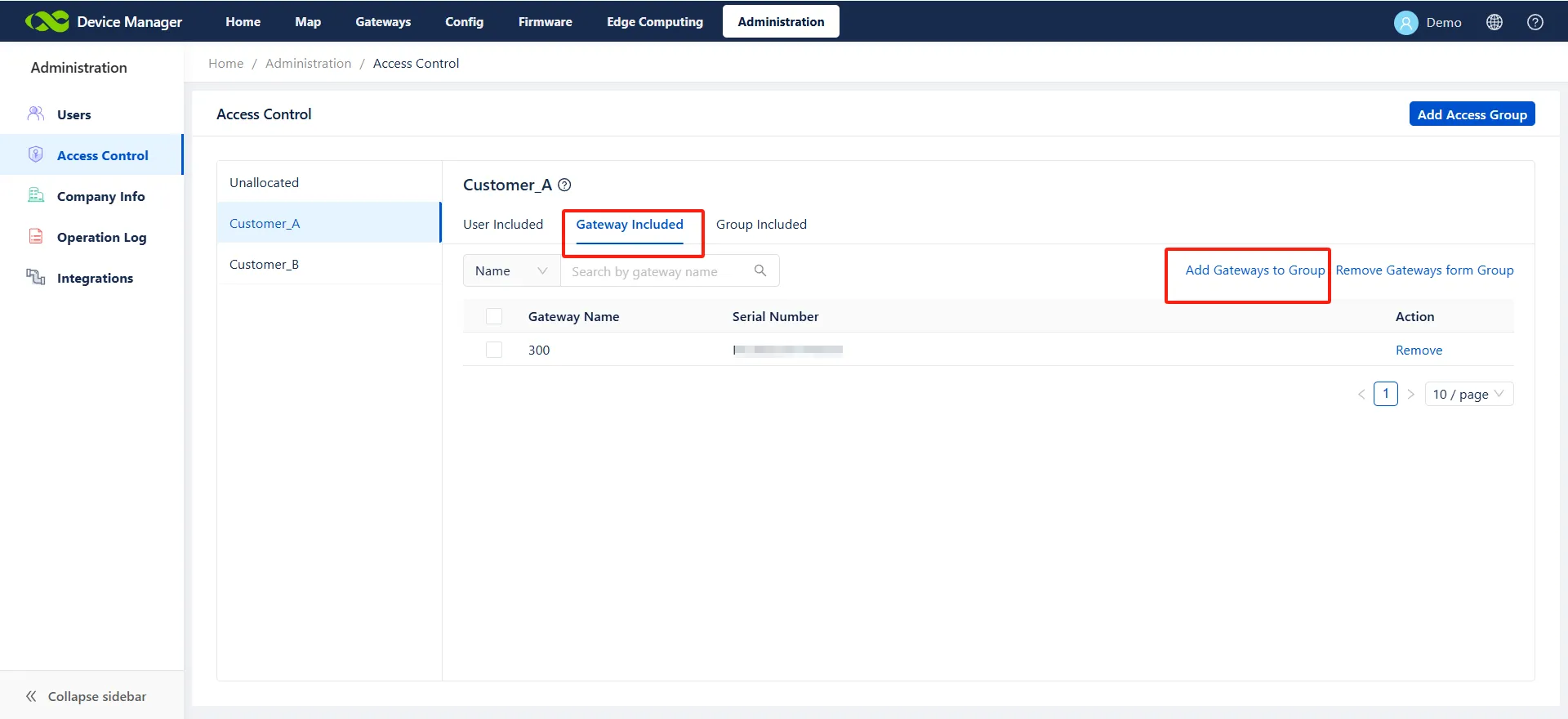
Figure 8-6 Allocating Gateways to a Group
Step 4: Allocate groups to the created permission group. Choose Group Included >> Add Groups to Access Control, select groups, and then click OK. Groups in the permission group can only be viewed and managed by users in this permission group.
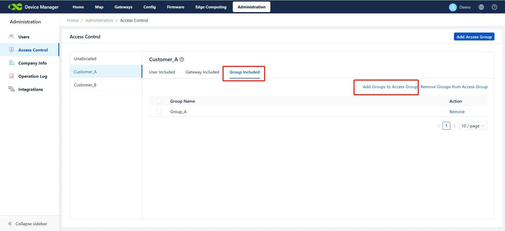
Figure 8-7 Allocating Groups to Access Control
Modifying a permission group:
When administrators need to modify users, devices, and groups in a permission group after permissions have changed, select a permission group, remove one or multiple devices, users, or groups from the permission group, and then add some devices, users or groups to the permission group.
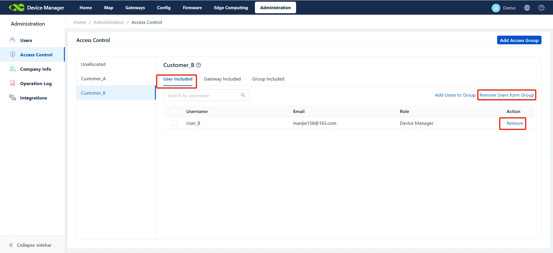
Figure 8-8 Modifying Permission Groups
[!CAUTION] New gateway devices, users, and groups are in the state of Unallocated by default. This means new gateways and groups can be viewed by all users, and new users can view all unallocated gateway devices and groups by default. Therefore, after creating a user, gateway device, or group, grant permissions for the user, gateway, and group as soon as possible.
8.3 Switch Organization
When a company external user is required to join an organization to provide external support, if the external user has registered an email account in DM, administrators can invite them to join the current organization by adding them as an "External User".
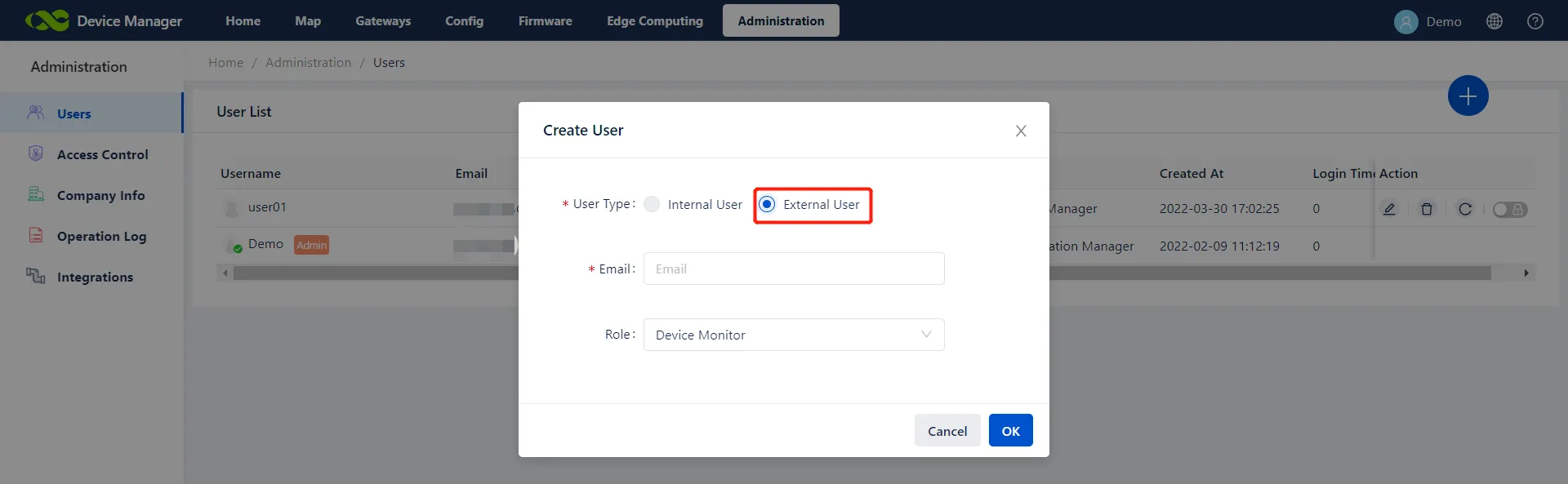
Figure 8-9 External User Support View
On the Administration >> Users page, click Add and select User Type as External User, fill in the email address of the external user and submit. An invitation email will be sent to this email. External users can join the current organization after accepting the invitation. At the same time, they can switch between multiple organizations in the personal center of their accounts:
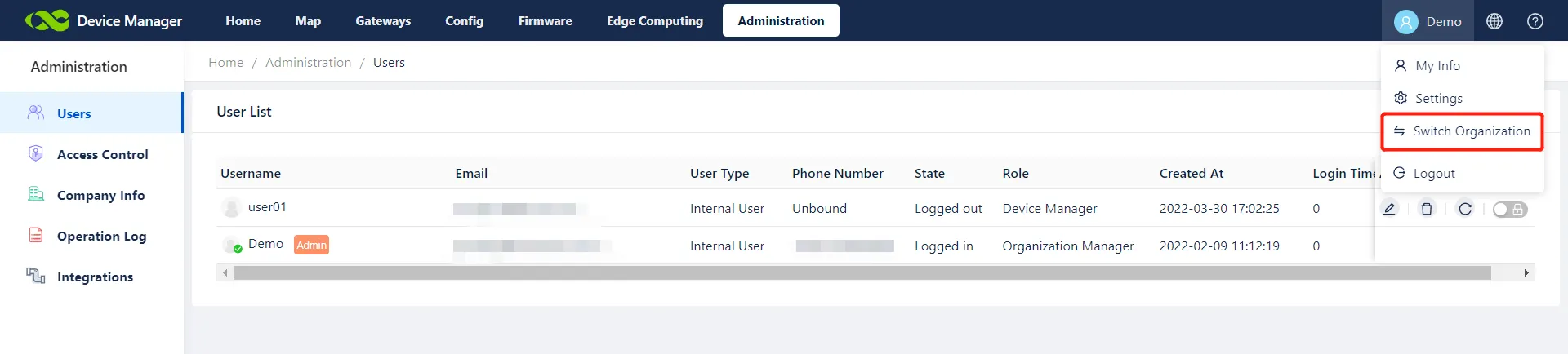
Figure 8-10 Switch Organization Options
Administrators can set user roles and add gateway permissions to this external user so that they can provide full technical support when accessing the organization without causing unnecessary data leakage.
8.4 Company Information
On the Administration >> Company Info page, administrators can maintain the background information of the current account's owner.
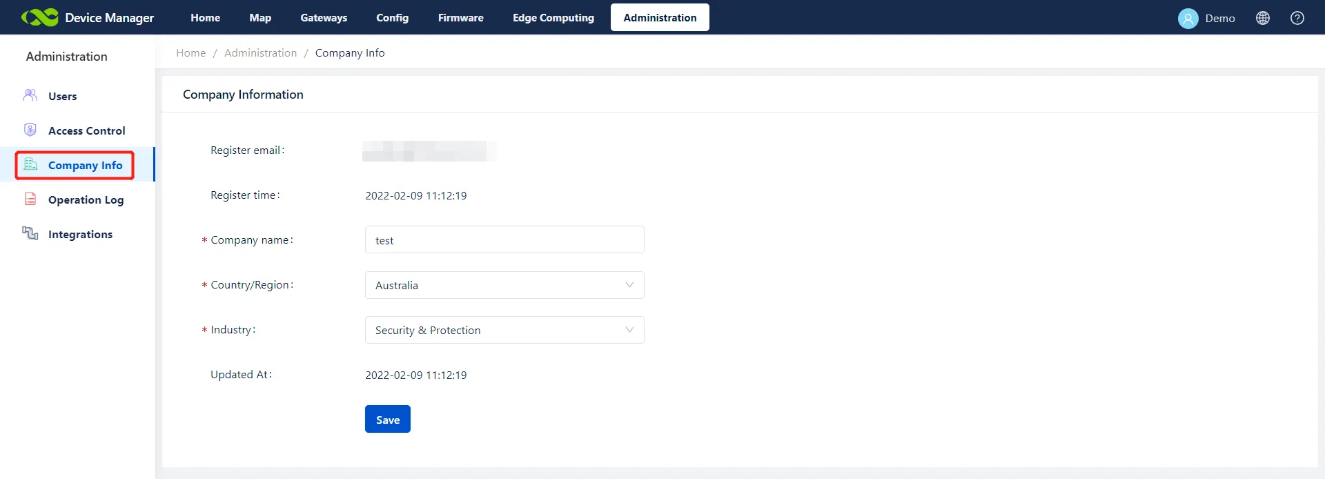
Figure 8-11 Company Information Page
8.5 System Logs
On the Administration >> Logs page, administrators can view system records about user login, device operation, firmware upgrade, and other information of the platform.
8.6 Integrations
When administrators need to push device-reported data such as data usage and location to third-party services, Device Manager's Integrations functionality can be utilized. Simply configure external server information on the platform (such as MQTT or Kafka servers) to establish connections between the platform and these external servers. The following example demonstrates integration with an external MQTT server:
- Go to Administration >> Integrations and click Add Integration.
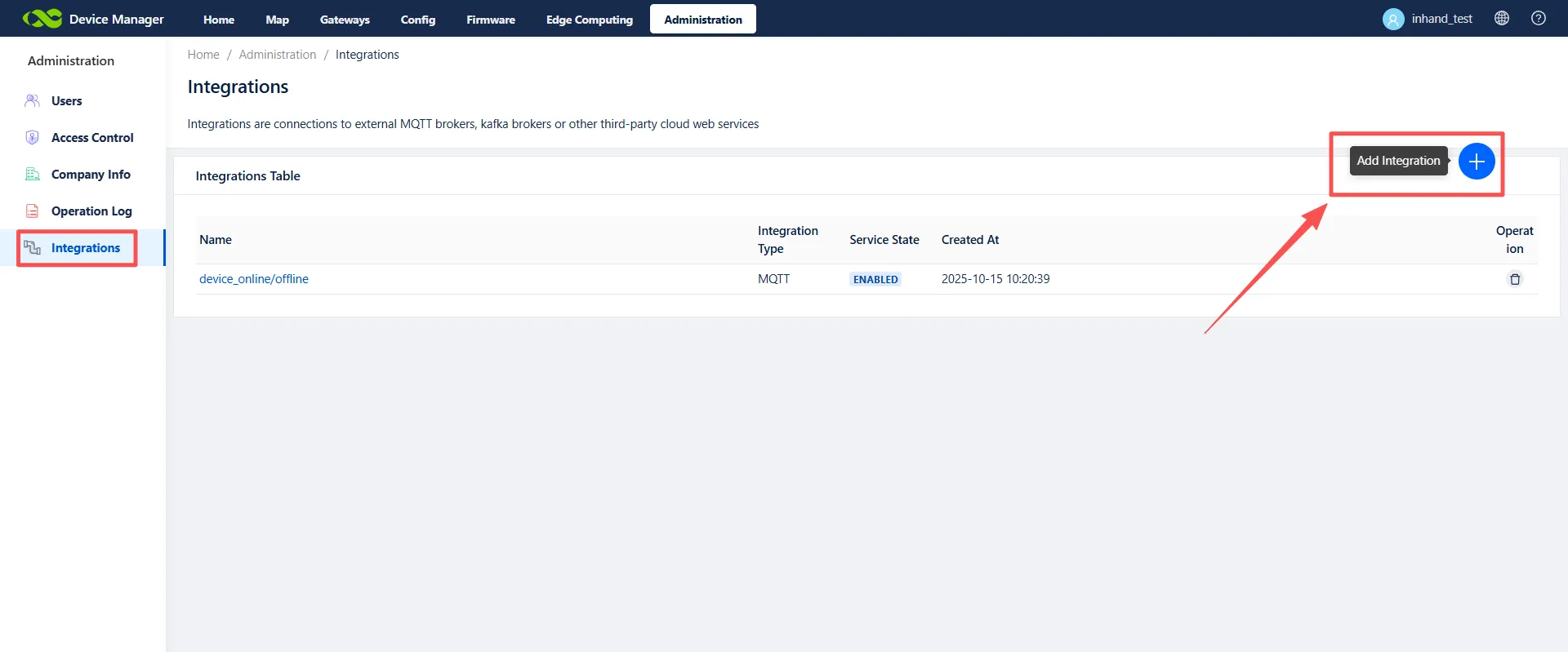
Figure 8-12 Adding an Integration
- Select the service type as MQTT and enter the corresponding server address, port, username, password, and other information for the MQTT service. Choose the event types to receive and define custom topics. The configuration shown below receives events such as device online/offline status, location, and device information via an open-source MQTT service (client ID, username, and password can be left blank).
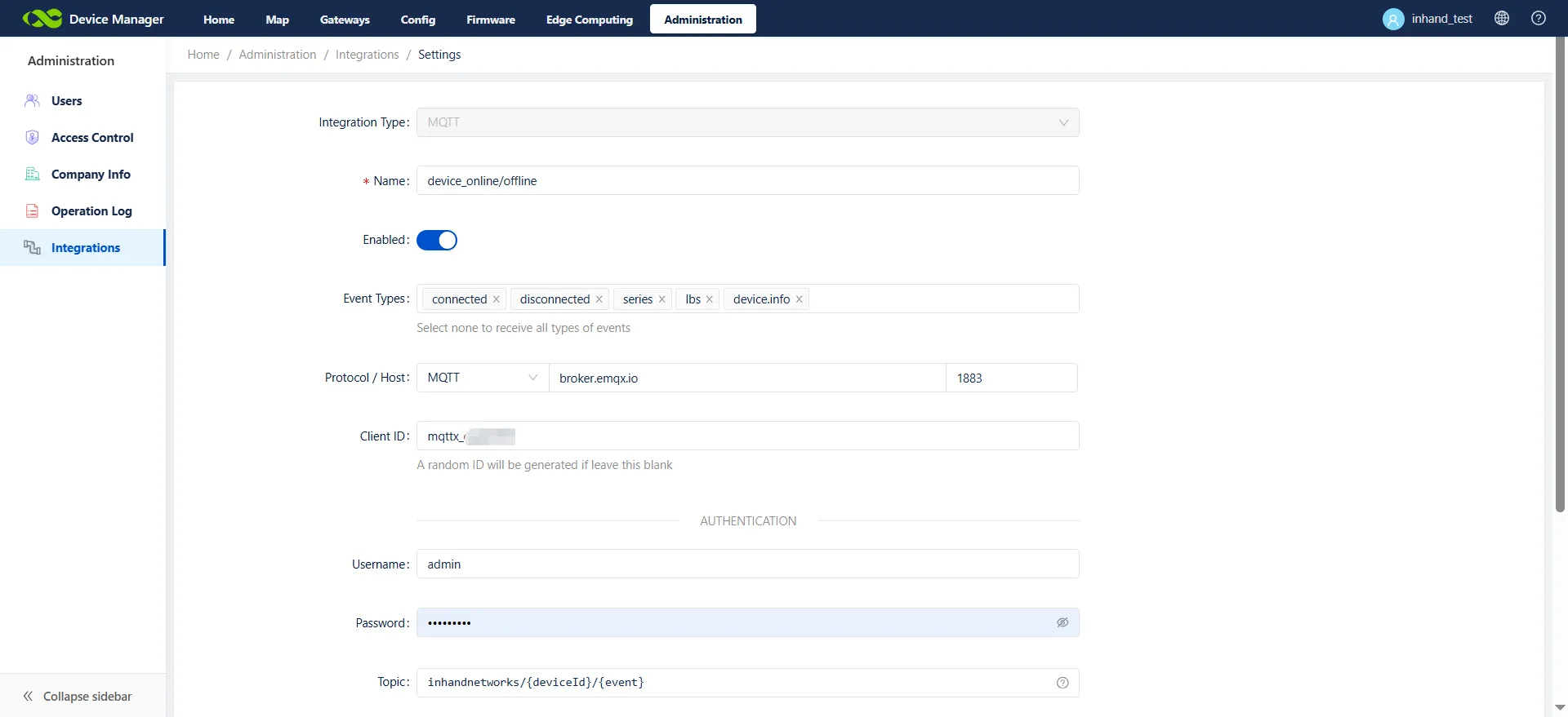
Figure 8-13 MQTT Service Configuration
| Event Type | Description | Trigger Time |
|---|---|---|
| connected | The device establishes a connection with Device Manager. | Immediately triggered. |
| disconnected | The device is disconnected from Device Manager. | Immediately triggered. |
| device.series | The device's time-sequential data such as flow usage. | The triggering time is determined by the local configuration of the device and is usually set to report once every 1 hour by default. |
| lbs | Cellular base station information, such as: MNC, MCC, LAC, CID. | The triggering time is determined by the local configuration of the device. |
| device.info | The basic information of the equipment, such as: serial number, MAC address, network port, IP, etc. | The device will report when it is launched on the platform. |
- Configure and connect to the MQTT service using MQTTX or other MQTT tools. Using MQTTX as an example:
- Click New Connection.
- Configure the MQTT server information (matching the settings in Device Manager).
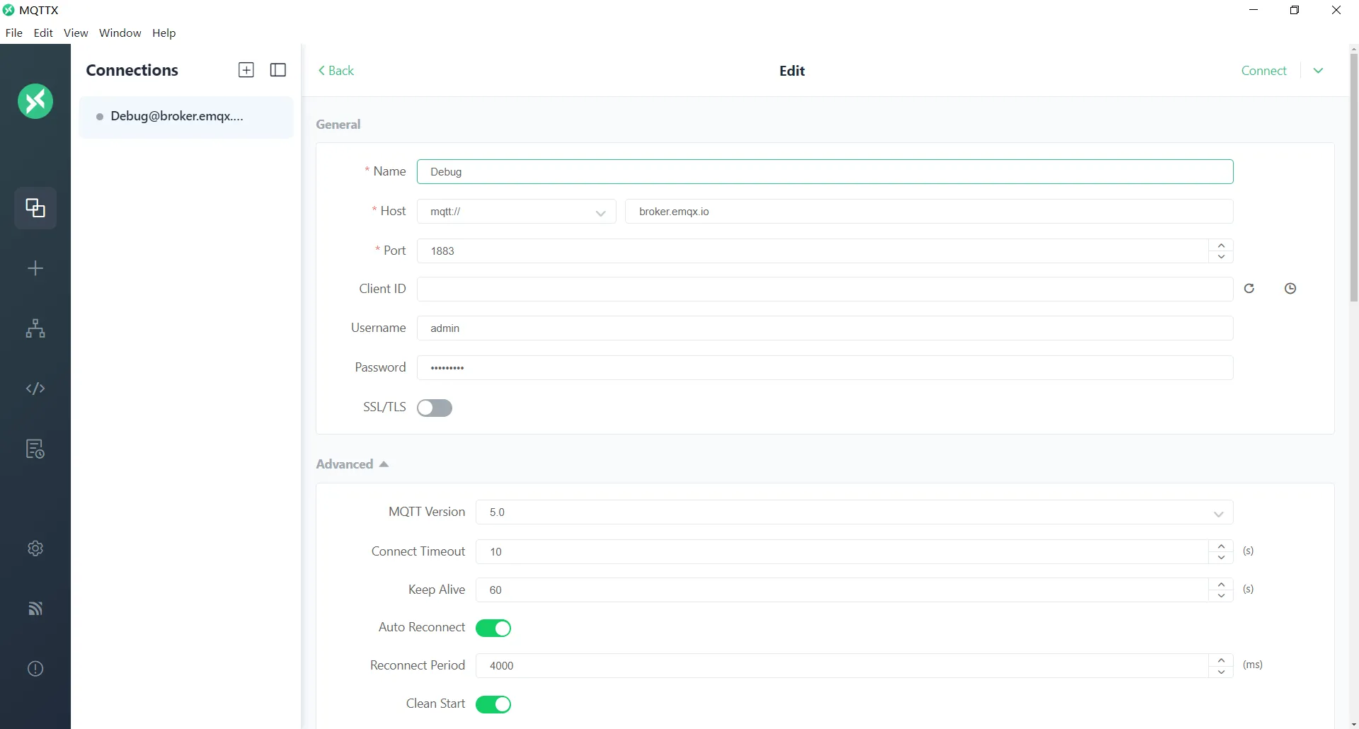
Figure 8-14 MQTTX Connection Configuration
- After configuration is complete, click Connect. A successful connection will be established. If the connection fails, please verify that the MQTT service is functioning properly or that the MQTT server information configured is correct.
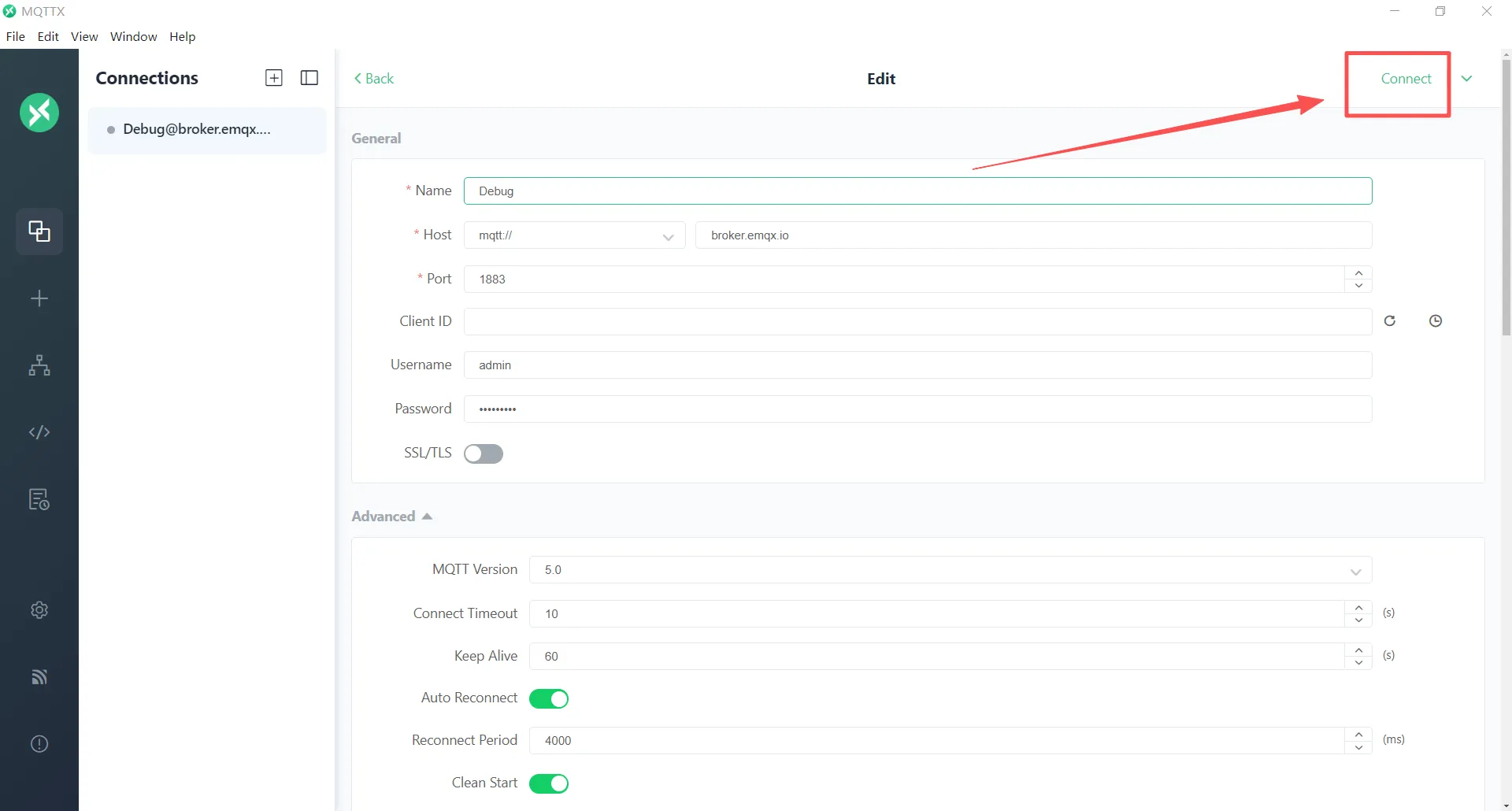
Figure 8-15 MQTTX Successful Connection
- In MQTTX, click Add Subscription, enter the topic to subscribe to, and save. For example:
inhandnetworks/+/+orinhandnetworks/#: Indicates subscribing to all topics prefixed withinhandnetworks/.inhandnetworks/{deviceId}/lbs: Indicates subscribing to location messages for a specific device.deviceIdis the unique identifier for the device in Device Manager.
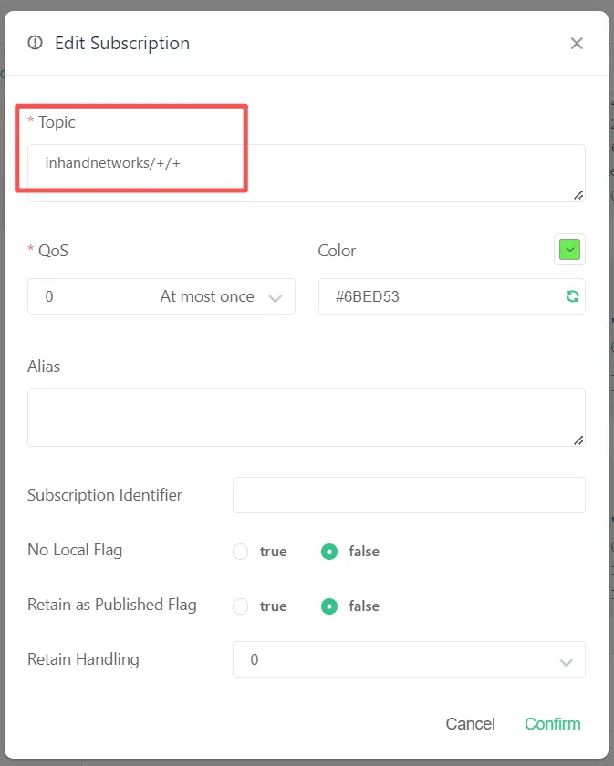
Figure 8-16 Adding an MQTT Subscription
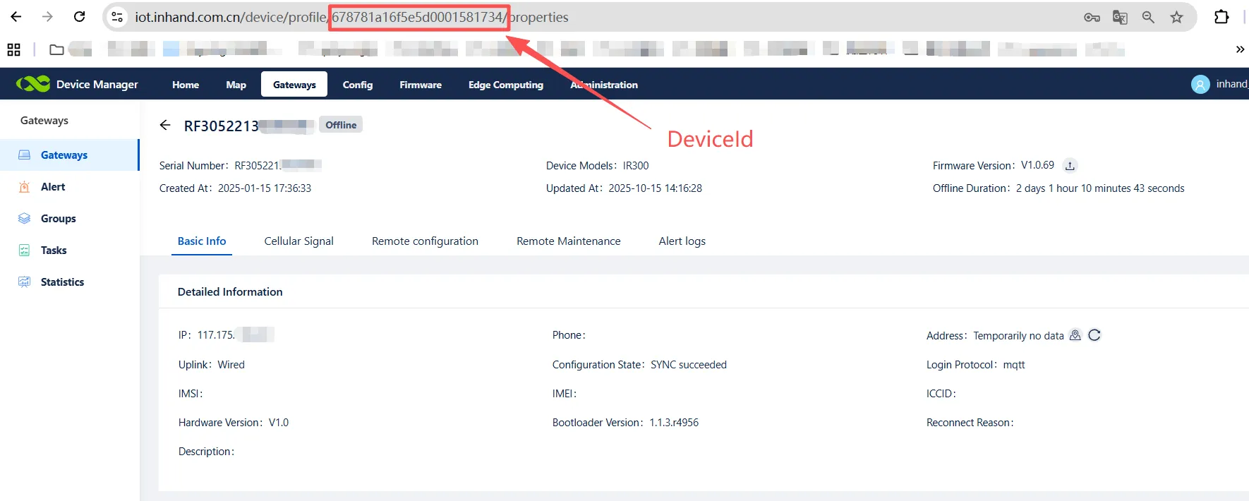
Figure 8-17 Subscription List in MQTTX
- Configuration is complete. When the device generates the selected event, the corresponding event notification will be immediately received.
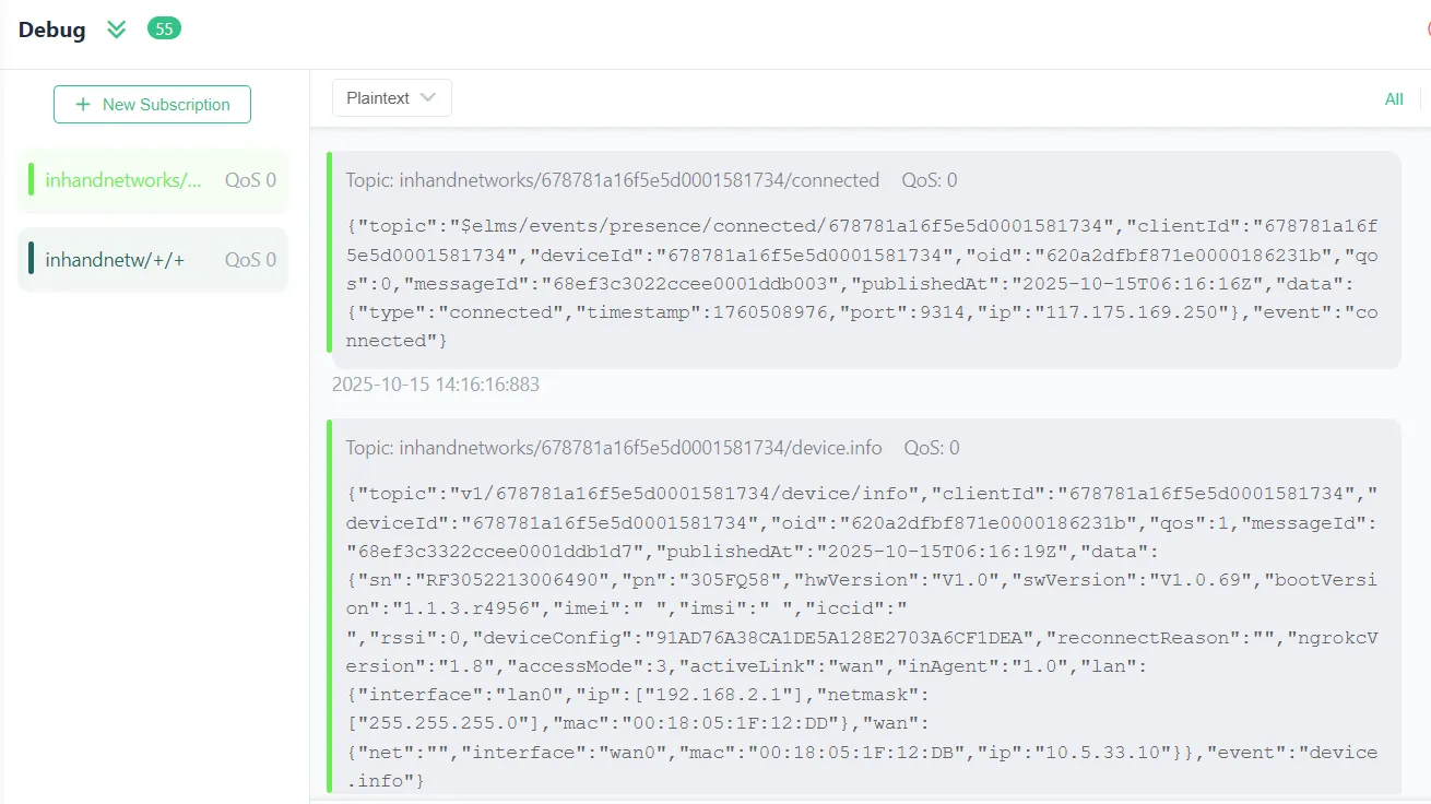
Figure 8-18 Receiving Event Notifications in MQTTX
9. DashBoard
On the Home page of DM, recent running status of gateway devices and system device information are displayed via charts:
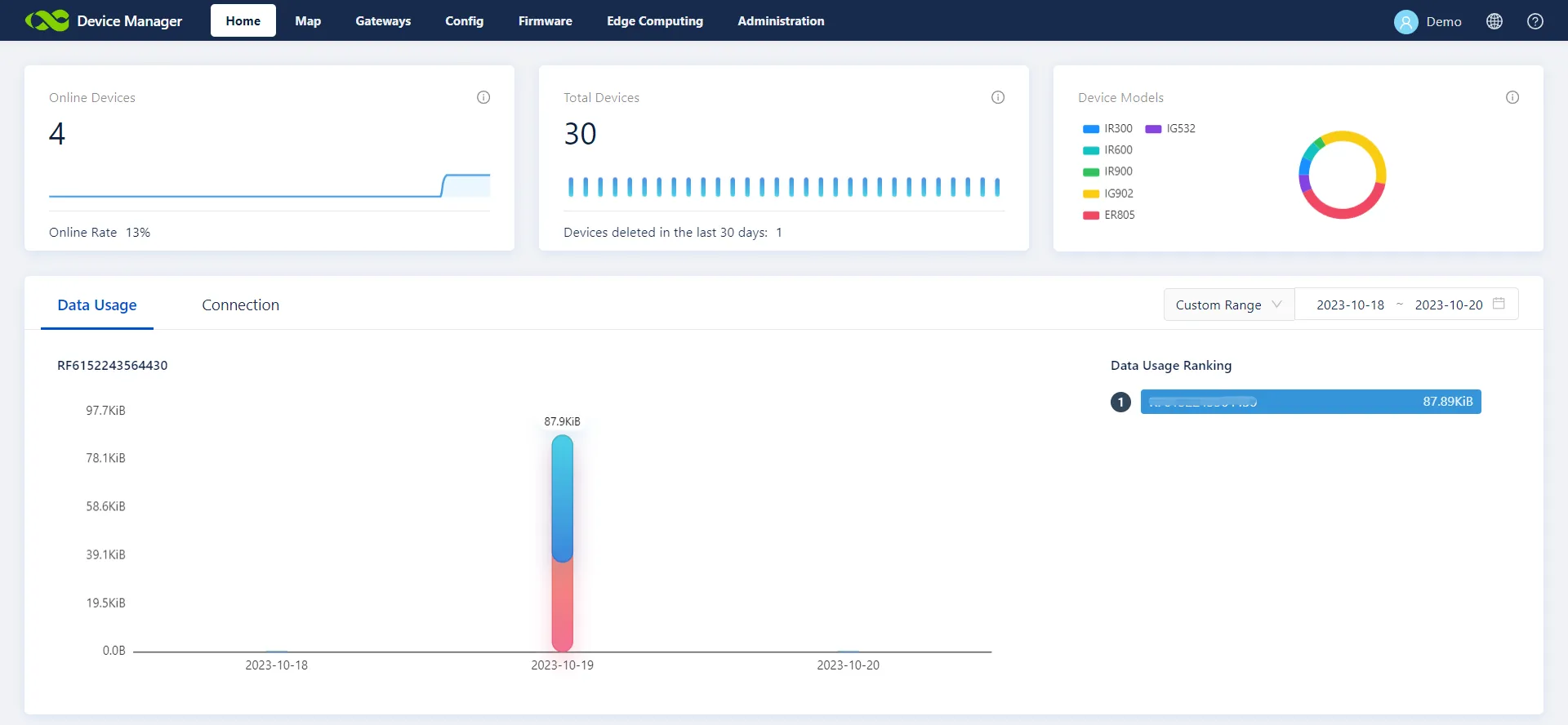
Figure 9-1 Device Manager Dashboard View
10. Appendix How to Connect Device to Network
Taking IR915 as an example, devices can be connected to the network in any of three ways: Ethernet (wired), SIM card, and Wi-Fi.
For more information about other networking methods, see the hardware user manual or visit the official website of InHand: https://www.inhandnetworks.com/
[!CAUTION] Disable the "cellular interface" when accessing the network without the SIM card; otherwise repeated dial-up is performed, interfering with the network connection.
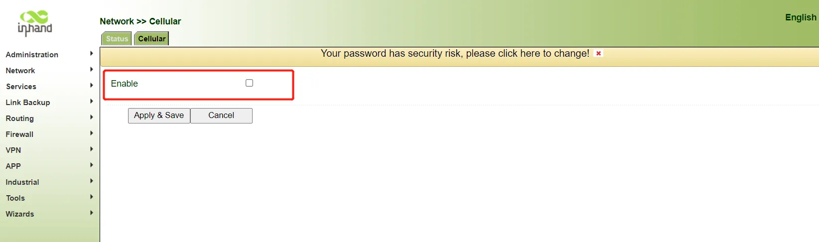
Figure 10-1 Cellular Interface Configuration
10.1 Method 1: Access the network through dial-up or SIM card
Step 1: Insert the SIM card into slot 1 and tighten the 4G LTE antenna to the ANT terminal. Connect the network cable to a PC and connect to the power supply.
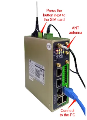
Figure 10-2 SIM Card and Antenna Installation
[!CAUTION] When inserting or removing the SIM card, you must disconnect the device from the power supply to avoid data loss or damage to the device.
Step 2: Open the browser and log in to the web page of the device. (See Method 2: Ethernet.)
Step 3: Choose Network >> Cellular >> Enable, and then click Apply & Save.
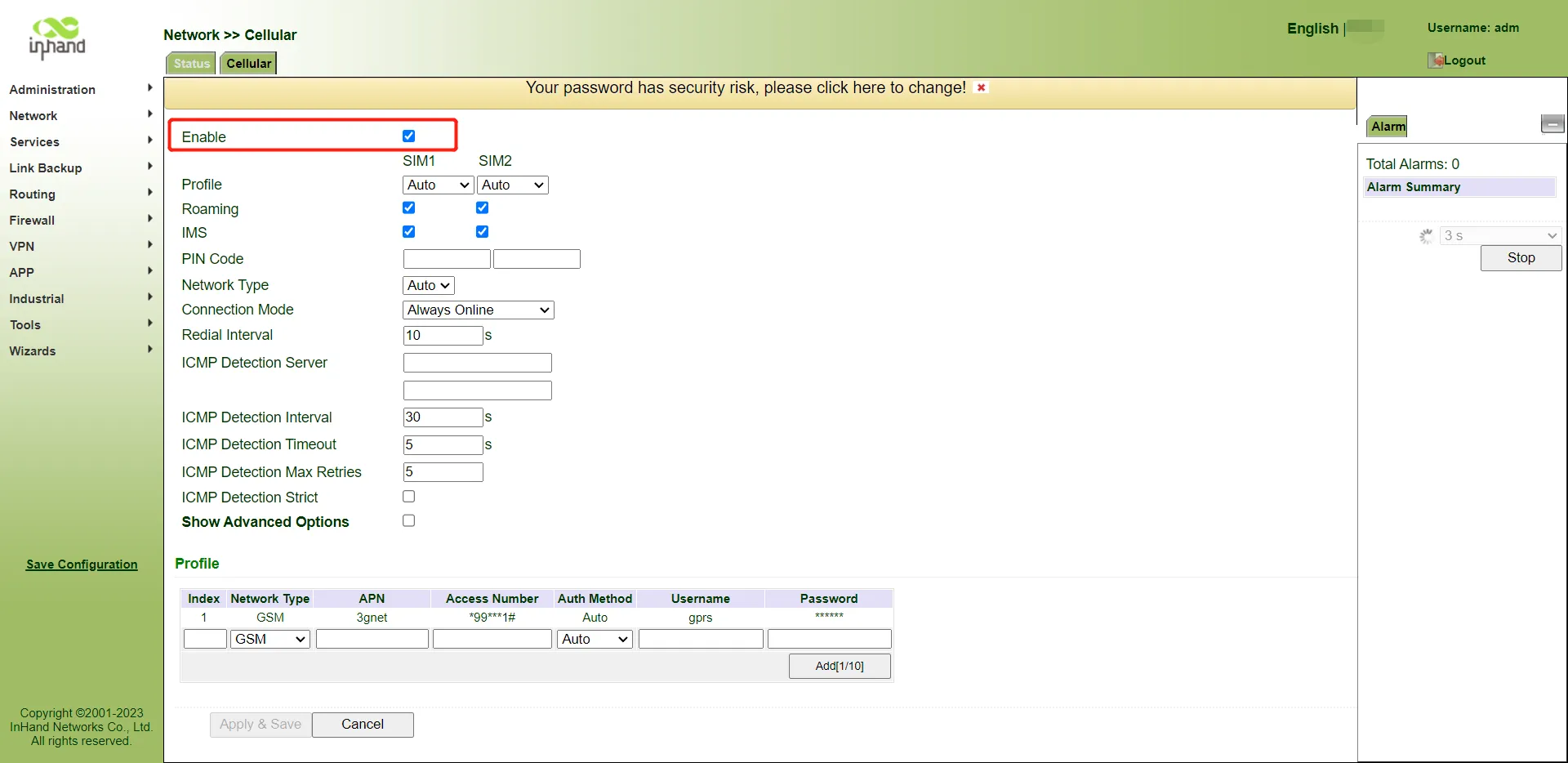
Figure 10-3 Enabling Cellular Connection
Step 4: Wait until the network connection status is Connected and an IP address is allocated. Then, the network is connected through the SIM card.
Step 5: For devices that support the dual-card mode and the SIM card is inserted to slot 2, select Dual SIM Enable.
10.2 Method 2: Ethernet
Step 1: Connect the power supply and network cable to the device, and connect the LAN (FE 1/1, FE1/2, FE1/3, or FE1/4) port to a PC and the WAN (FE0/1) port to the Internet.
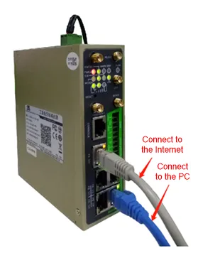
Figure 10-4 Ethernet Port Connections
Step 2: Set the IP addresses of the PC and gateway to be in the same network segment.
1. Method 1: Automatically get the IP address (recommended)
2. Method 2: Use a fixed IP address and set the PC and gateway to be in the same network segment. Set the initial IP address of the device to 192.168.2.1 and the subnet mask to 255.255.255.0. Select Use the following IP address. Enter an IP address ranging from 192.168.2.2 to 192.168.2.254, a subnet mask 255.255.255.0, and the default gateway 192.168.2.1, and then click OK.
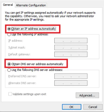
Figure 10-5 Automatic IP Address Configuration
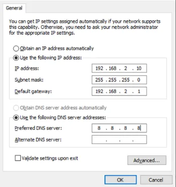
Figure 10-6 Fixed IP Address Configuration
Step 3: In the address bar of the browser, enter the default device address 192.168.2.1 to enter the device web management page. (If it prompts that the website is insecure, unfold the menu and click Go Still or Proceed.)
Step 4: Log in to the device.
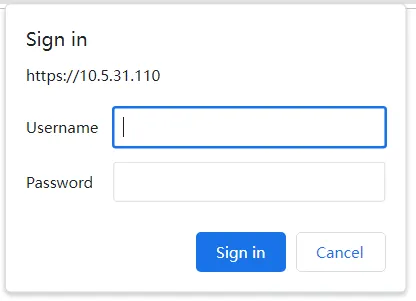
Figure 10-7 Device Web Login Interface
Step 5: Choose Network >> New WAN. Configure an IP address for the WAN port to connect the router to the Internet.
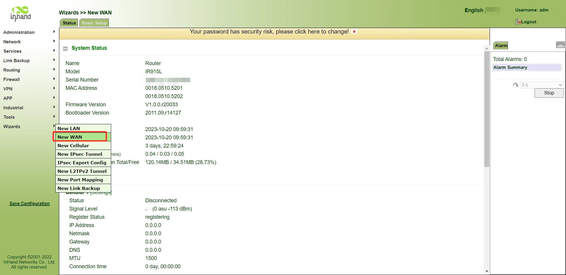
Figure 10-8 New WAN Configuration
Step 6: It is recommended to select Dynamic Address (DHCP). If Static IP Address is selected, manually configure the network parameters, and then click Apply & Save.
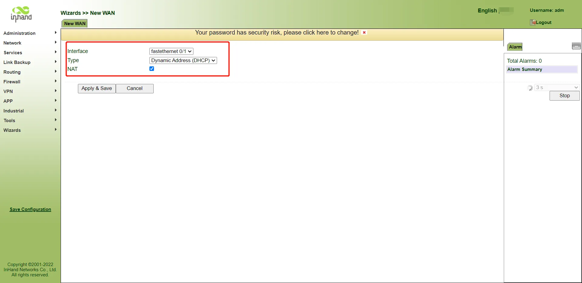
Figure 10-9 Dynamic Address (DHCP) Configuration
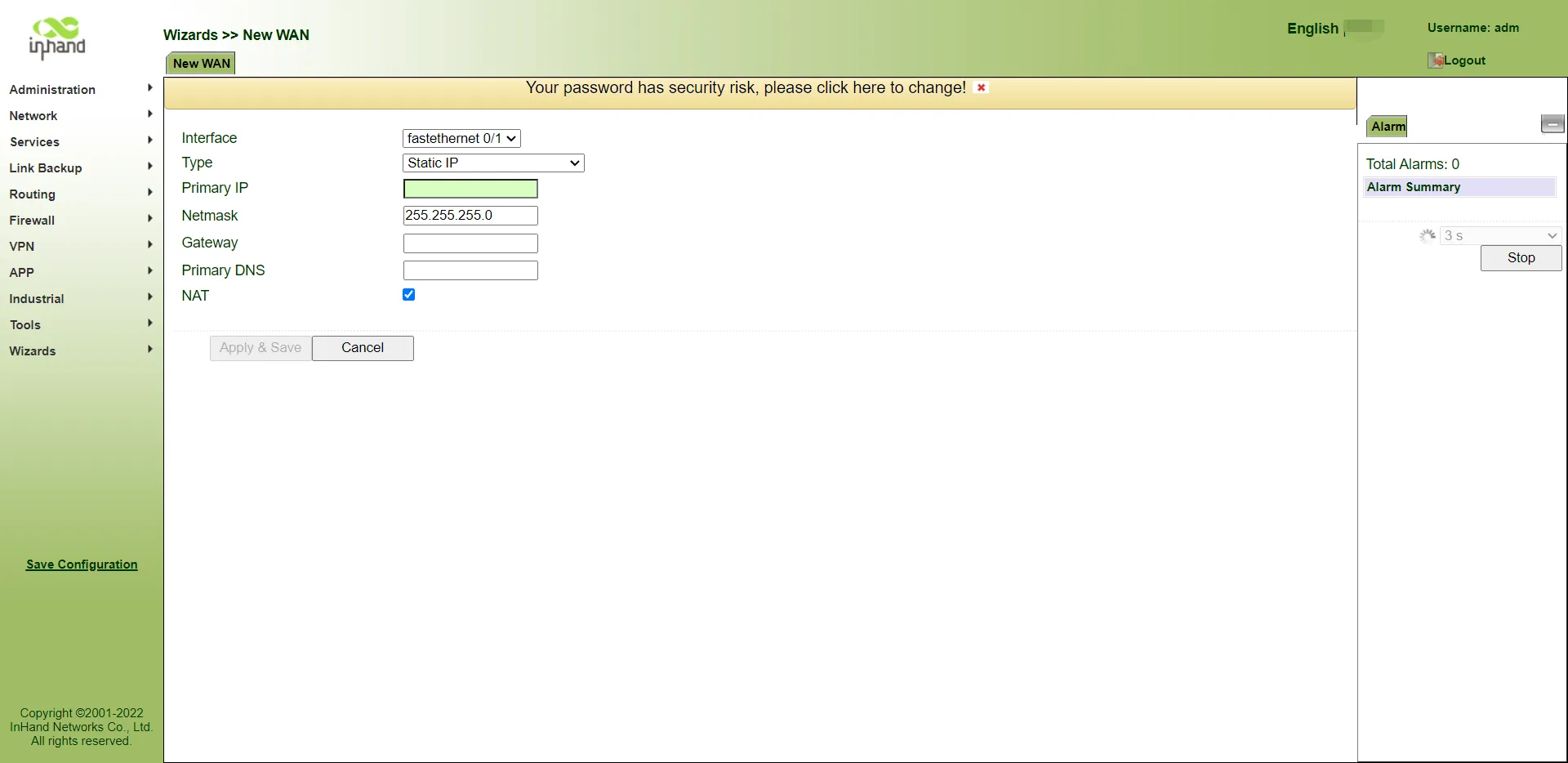
Figure 10-10 Static IP Address Configuration
Step 7: Choose Tools >> Ping. In the Host field, enter a common website (e.g., a reliable public server) to test whether the device can connect to the Internet. If data transmission is displayed, the device can connect to the Internet.
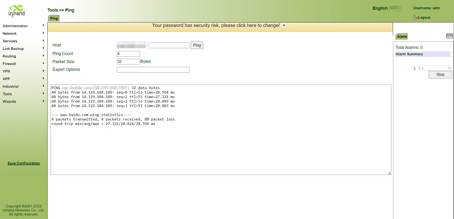
Figure 10-11 Ping Test for Network Verification
10.3 Method 3: Wi-Fi
Step 1: Connect the Wi-Fi antenna to the WLAN port and use a network cable to connect the PC and the power supply.
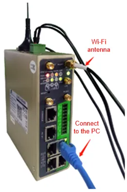
Figure 10-12 Wi-Fi Antenna Connection
Step 2: Set the IP addresses of the PC and the gateway to be in the same network segment. On a browser, visit the web management page of the gateway. (See Method 2: Ethernet).
Step 3: Choose Network >> WLAN, enable the WLAN port, and configure the parameters.
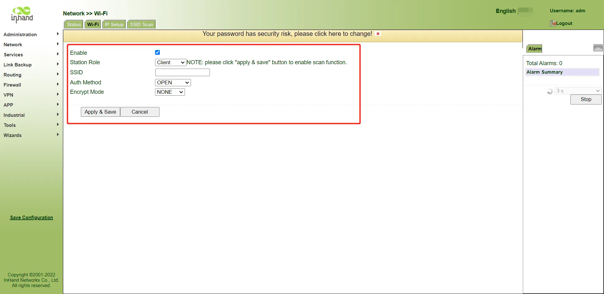
Figure 10-13 WLAN Port Configuration
Step 4: Click the Status tab. The network connection status should be Connected.
Step 5: Choose Wizards >> New WLAN, and configure the parameters.
Step 6: Choose Firewall >> Network Address Translation (NAT). If a connection named dot11radio 1 is displayed, Wi-Fi is connected.
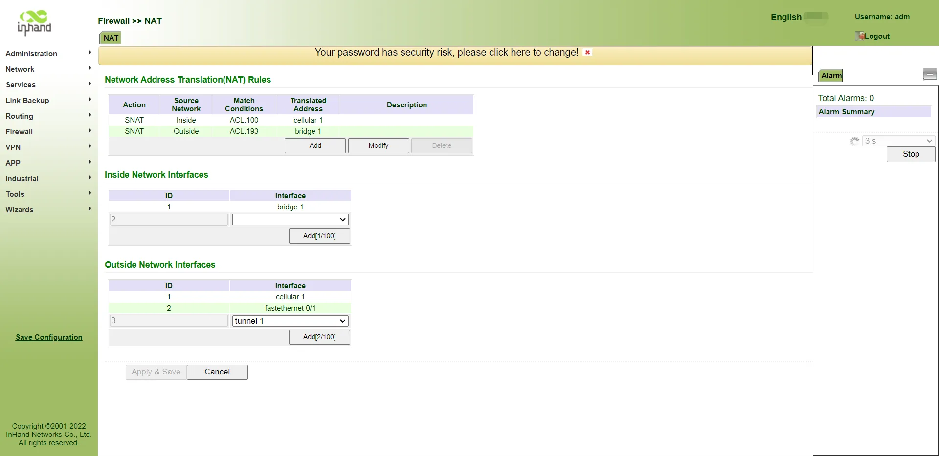
Figure 10-14 NAT Configuration Verification